2014 Ram 1500 Exhaust System Diagram
Let's dive into the exhaust system of the 2014 Ram 1500. Understanding this system is crucial for diagnostics, repairs, modifications, and even just general knowledge about your truck. This article will break down the exhaust system diagram, explaining each component and its function, and provide you with the information you need to confidently work on your Ram 1500.
Why Understanding the Diagram Matters
The exhaust system diagram is your roadmap when dealing with any issue related to exhaust. It provides a visual representation of all the components, their locations, and how they interact. This is invaluable for:
- Troubleshooting: Identifying the source of exhaust leaks, unusual noises, or performance issues.
- Repairs: Replacing damaged parts correctly and ensuring proper fitment.
- Modifications: Planning and executing aftermarket exhaust upgrades or modifications.
- General Maintenance: Understanding the system allows you to perform preventative maintenance and identify potential problems early.
- Learning: Simply expanding your knowledge about automotive systems.
Key Specs and Main Parts of the 2014 Ram 1500 Exhaust
The 2014 Ram 1500 exhaust system varies slightly depending on the engine option (3.6L V6, 5.7L Hemi V8), cab configuration, and drivetrain (2WD/4WD). However, the fundamental components and their functions remain consistent. Key components include:
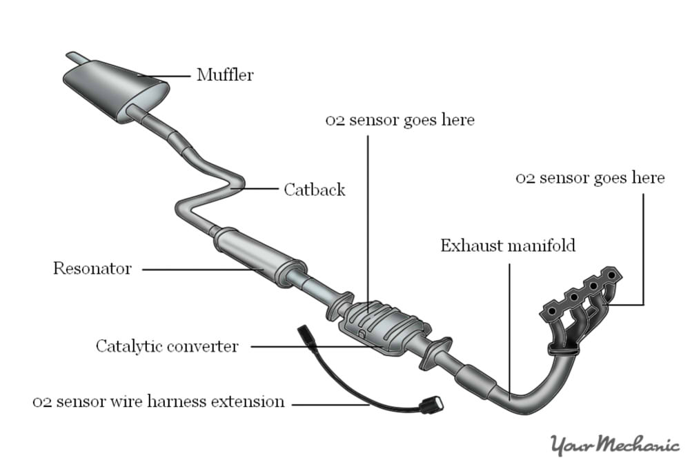
- Exhaust Manifolds: These are bolted directly to the engine cylinder heads. They collect exhaust gases from each cylinder. For the Hemi V8, there are two manifolds, one for each bank of cylinders.
- Catalytic Converters: Crucial for emissions control, the catalytic converters use chemical reactions to reduce harmful pollutants (hydrocarbons, carbon monoxide, and nitrogen oxides) into less harmful substances. Most 2014 Ram 1500s have two catalytic converters.
- Oxygen Sensors (O2 Sensors): These sensors monitor the oxygen content in the exhaust stream before (upstream) and after (downstream) the catalytic converters. The Engine Control Module (ECM) uses this information to optimize the air-fuel mixture for efficient combustion and emissions control.
- Resonator: This component helps to dampen certain frequencies in the exhaust stream, reducing unwanted noise and drone. It's usually a cylindrical chamber located mid-pipe.
- Muffler: The muffler is the main noise reduction device in the exhaust system. It uses baffles and chambers to cancel out sound waves.
- Tailpipe: The tailpipe is the final section of the exhaust system, directing exhaust gases away from the vehicle.
- Exhaust Pipes: These connect all the other components together. They are typically made of aluminized steel or stainless steel.
- Hangers and Mounts: Rubber hangers and metal brackets secure the exhaust system to the vehicle's undercarriage, preventing vibrations and movement.
- Flanges and Gaskets: These are used to create sealed connections between exhaust components. Gaskets are crucial for preventing exhaust leaks.
Understanding the Diagram Symbols
Exhaust system diagrams use a standardized set of symbols to represent different components and connections. Here's a breakdown of common symbols:
- Solid Lines: Represent exhaust pipes or tubing. The thickness of the line may indicate the pipe's diameter.
- Dashed Lines: May indicate vacuum lines or other related systems (like the EGR system, if present, though less common on the 2014 Ram 1500).
- Rectangles: Often used to represent catalytic converters, mufflers, or resonators. The diagram may include labels within the rectangle to identify the specific component.
- Circles/Ovals: Typically represent oxygen sensors. Arrows pointing into or out of the circle may indicate the sensor's location (upstream or downstream of the catalytic converter).
- Flanges: Usually depicted as two parallel lines connected by short perpendicular lines, indicating a bolted connection.
- Hangers/Mounts: Can vary, but often shown as small hooks or loops connecting the exhaust pipe to the vehicle frame.
- Arrows: Indicate the direction of exhaust gas flow.
Colors, if present, are typically used to differentiate between different sections of the exhaust system or to highlight specific components. The legend on the diagram will explain the meaning of each color.
How the Exhaust System Works
The exhaust system's primary function is to safely and efficiently remove combustion byproducts from the engine. Here's a step-by-step explanation:
- Exhaust Collection: Exhaust gases are forced out of the engine cylinders and into the exhaust manifolds.
- Catalytic Conversion: The exhaust gases then flow through the catalytic converters, where harmful pollutants are converted into less harmful substances. The converter relies on a heated core and specific catalysts (platinum, palladium, rhodium) to facilitate the chemical reactions.
- Oxygen Monitoring: Oxygen sensors monitor the oxygen levels before and after the catalytic converters. This data is sent to the ECM, which adjusts the air-fuel mixture to optimize combustion and ensure the catalytic converters are functioning efficiently.
- Noise Reduction: The exhaust gases pass through the resonator (if equipped) and the muffler. These components reduce noise levels by canceling out sound waves.
- Exhaust Discharge: Finally, the exhaust gases exit the vehicle through the tailpipe.
Real-World Use and Troubleshooting
Here are some common problems you might encounter with your 2014 Ram 1500 exhaust system and how the diagram can help:
- Exhaust Leak: A hissing or roaring noise, especially under acceleration, often indicates an exhaust leak. Use the diagram to locate all the flanges and connections. Visually inspect these areas for signs of corrosion, cracks, or loose bolts. Listen closely around these areas with the engine running to pinpoint the leak. Common leak locations include manifold gaskets, flange connections, and rusted-out sections of pipe.
- Catalytic Converter Failure: A clogged or failed catalytic converter can cause a loss of power, poor fuel economy, and a "rotten egg" smell. The check engine light will likely illuminate, with codes related to catalytic converter efficiency (e.g., P0420, P0430). The diagram helps you locate the catalytic converter(s) for inspection or replacement. Note: Diagnosing a faulty catalytic converter often requires specialized tools and knowledge.
- Oxygen Sensor Issues: Faulty oxygen sensors can cause a variety of problems, including poor fuel economy, rough idling, and a check engine light. The diagram will show you the location of each oxygen sensor. You can use a multimeter to test the sensors' resistance or voltage output.
- Rattling or Vibration: A rattling or vibrating exhaust system can be caused by loose hangers, damaged pipes, or a failing muffler. Use the diagram to inspect all the hangers and mounts. Make sure they are securely attached and in good condition. Also, check the exhaust pipes for dents or cracks.
Safety Precautions
Working on the exhaust system involves certain risks. Always take the following precautions:
- Allow the Exhaust System to Cool Down: The exhaust system gets extremely hot. Never work on it immediately after driving the vehicle. Allow ample time for it to cool down completely to prevent severe burns.
- Wear Safety Glasses: Protect your eyes from debris and rust particles.
- Use Gloves: Wear work gloves to protect your hands from sharp edges and hot surfaces.
- Work in a Well-Ventilated Area: Exhaust gases contain carbon monoxide, a deadly gas. Work outdoors or in a well-ventilated garage.
- Use Jack Stands: If you need to lift the vehicle, use jack stands to support it securely. Never work under a vehicle supported only by a jack.
- Be Aware of Hot Surfaces: Even after the exhaust system has cooled down somewhat, certain areas may still be hot. Use caution and avoid touching the catalytic converter or exhaust manifold.
By understanding the exhaust system diagram and following these safety precautions, you can confidently diagnose and repair exhaust-related issues on your 2014 Ram 1500. Good luck!
We have the 2014 Ram 1500 Exhaust System Diagram available for download. It includes detailed views of the components and their placement. It will certainly aid in your diagnostic and repair work. Contact us via the contact form to access the file.