
2014 Silverado Front Suspension Diagram
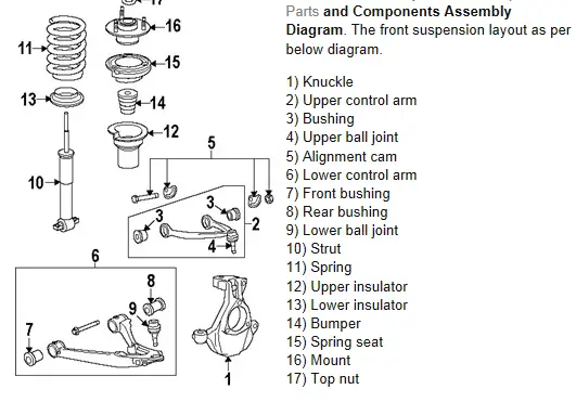
Let's dive into the front suspension system of the 2014 Chevrolet Silverado. Understanding this system is crucial for anyone performing repairs, upgrades, or even just trying to diagnose a pesky front-end noise. This breakdown will equip you with the knowledge to interpret a suspension diagram and confidently tackle related maintenance tasks.
Purpose of a 2014 Silverado Front Suspension Diagram
A front suspension diagram serves as a visual roadmap to the entire system. It's more than just a pretty picture; it's an invaluable tool for:
- Diagnosis: Pinpointing the source of problems like clunking noises, uneven tire wear, or poor handling. The diagram helps you identify the components most likely responsible.
- Repair: Guiding you through the disassembly and reassembly process. Proper torque specs and component orientation are vital, and the diagram provides a visual reference.
- Modification: Planning and executing suspension upgrades, such as lift kits, leveling kits, or performance shocks. Understanding the factory setup is essential before making changes.
- Learning: Gaining a deeper understanding of how your vehicle's suspension works and how the various components interact.
Key Specs and Main Parts
The 2014 Silverado typically utilizes an independent front suspension system, specifically a coil-over-strut design. Here's a breakdown of the key components you'll find in the diagram:
- Upper Control Arm (UCA): The upper control arm connects the upper portion of the wheel hub assembly to the vehicle's frame. It allows for vertical wheel movement while maintaining proper wheel alignment.
- Lower Control Arm (LCA): Similarly, the lower control arm connects the lower portion of the wheel hub assembly to the frame. It bears a significant load and often acts as the mounting point for the coil spring and shock absorber.
- Coil Spring: The coil spring absorbs vertical impacts from the road, providing a comfortable ride. Its spring rate dictates how much it compresses under a given load.
- Shock Absorber (Strut): Also known as a damper, the shock absorber controls the compression and rebound of the coil spring, preventing excessive bouncing and maintaining tire contact with the road. In this strut design, the shock absorber is integrated into the same unit as the spring.
- Steering Knuckle (Spindle): The steering knuckle houses the wheel hub, bearings, and brake rotor. It pivots to allow the wheels to steer.
- Wheel Hub Assembly: The wheel hub assembly contains the bearings that allow the wheel to rotate freely.
- Tie Rod Ends (Inner & Outer): The tie rod ends connect the steering rack to the steering knuckle, transmitting steering inputs to the wheels. They are adjustable to control toe alignment.
- Sway Bar (Stabilizer Bar): The sway bar connects the left and right sides of the suspension, reducing body roll during cornering. It's typically linked to the lower control arms via sway bar links.
- Sway Bar Links: These connect the sway bar to the suspension components (usually the lower control arm). They are subject to wear and can cause clunking noises if worn out.
- Bump Stops: These rubber or urethane stops prevent the suspension from bottoming out, protecting the components from damage.
Key specs related to these components include:
- Torque Specifications: The specific torque values for each bolt and nut, critical for proper assembly and preventing loosening or damage.
- Alignment Angles: Camber, caster, and toe angles, which determine how the wheels are positioned relative to the vehicle. These angles affect handling, tire wear, and stability.
- Ride Height: The distance between the ground and specific points on the vehicle's frame or body, indicating the suspension's overall condition and level.
Understanding the Diagram's Symbols
Suspension diagrams aren't just pictures; they're technical drawings with specific conventions. Understanding these conventions allows you to extract the most information from the diagram:
- Lines: Solid lines typically represent physical components, while dashed lines may indicate hidden parts or motion paths. Line thickness can sometimes indicate the relative size or importance of a component.
- Arrows: Arrows often indicate the direction of movement or force. For example, an arrow pointing towards a coil spring might indicate the direction of compression under load.
- Colors: While not always present, colors can be used to differentiate between different systems or components. For example, the steering system might be highlighted in one color, while the suspension components are another.
- Labels & Callouts: These identify each component by name and often include part numbers. Look for numbered circles or boxes with corresponding descriptions.
- Fastener Symbols: Different symbols represent different types of fasteners, such as bolts, nuts, screws, and rivets. The diagram may also indicate the fastener size and grade.
Pay close attention to the legend or key that accompanies the diagram. This legend explains the meaning of each symbol and convention used.
How the 2014 Silverado Front Suspension Works
In the 2014 Silverado's independent front suspension, each wheel responds independently to road conditions. When a wheel encounters a bump, the coil spring compresses, absorbing the impact. The shock absorber dampens the spring's oscillation, preventing excessive bouncing. The control arms allow the wheel to move vertically while maintaining proper alignment. The sway bar resists body roll during cornering by transferring force between the left and right sides of the suspension.
The steering system is connected to the steering knuckles via tie rod ends. When the driver turns the steering wheel, the steering rack pushes or pulls on the tie rod ends, causing the steering knuckles to pivot and steer the wheels.
This independent design provides a more comfortable ride and better handling compared to a traditional solid axle suspension. However, it also requires more components and can be more complex to repair.
Real-World Use: Basic Troubleshooting
Here are some common suspension problems and how the diagram can help you diagnose them:
- Clunking Noise: Common culprits include worn sway bar links, loose ball joints, or worn shock absorbers. The diagram helps you locate these components and inspect them for play or damage.
- Uneven Tire Wear: Misalignment is a common cause. The diagram shows the location of the tie rod ends and control arm adjustments, which are used to correct alignment angles.
- Excessive Bouncing: Worn shock absorbers are the most likely cause. The diagram clearly shows the location of the shock absorbers for inspection and replacement.
- Poor Handling: Can be caused by a variety of issues, including worn shocks, loose ball joints, or damaged control arm bushings. The diagram helps you systematically inspect each component.
Important: Always consult the vehicle's service manual for specific diagnostic procedures and torque specifications.
Safety Considerations
Working on suspension systems can be dangerous due to the potential for stored energy in the coil springs. Never disassemble a strut assembly without using a proper spring compressor. Failure to do so can result in serious injury or death.
Here are some key safety precautions:
- Use a Spring Compressor: Always use a properly rated spring compressor to safely remove and install coil springs.
- Support the Vehicle: Always use jack stands to support the vehicle before working underneath it. Never rely solely on a jack.
- Wear Safety Glasses: Protect your eyes from debris and flying objects.
- Consult the Service Manual: Follow the manufacturer's instructions for disassembly and reassembly.
- Torque Specifications: Always use a torque wrench to tighten fasteners to the specified torque.
Be especially careful when working with:
- Coil Springs: Store significant energy.
- Ball Joints: Can separate unexpectedly if worn or damaged.
- Hydraulic Components: Can leak fluid under pressure.
If you're not comfortable working on suspension systems, it's best to consult a qualified mechanic.
This article provides a solid foundation for understanding the 2014 Silverado's front suspension. Armed with this knowledge, you can confidently diagnose problems, plan modifications, and perform basic repairs. Remember to always prioritize safety and consult the vehicle's service manual for specific instructions and torque specifications.