2014 Silverado Radio Wiring Harness Diagram
Alright, let's dive into the 2014 Silverado radio wiring harness diagram. Whether you're swapping out the factory head unit, adding aftermarket amplifiers, or just troubleshooting a pesky electrical issue, understanding this diagram is absolutely crucial. This isn’t just a pretty picture; it's your roadmap to the audio system's nervous system.
Purpose of the Diagram
Why bother with a wiring diagram? Simple: accuracy and safety. Guessing which wire does what is a recipe for disaster – blown fuses, fried components, or even electrical fires. This diagram gives you a clear visual representation of every wire's function, making tasks like:
- Replacing the factory radio with an aftermarket unit.
- Adding amplifiers, subwoofers, and other audio enhancements.
- Troubleshooting audio problems (no sound, static, etc.).
- Installing remote start systems that integrate with the factory radio.
- Understanding the vehicle's overall electrical system better.
Much easier and safer when you know what you're doing, right?
Key Specs and Main Parts
The 2014 Silverado radio wiring harness is more than just a bundle of wires; it's a complex network that interfaces with various vehicle systems. Key specs you'll want to know include the voltage (typically 12V DC), the wire gauge (thickness), and the amperage rating of associated fuses. Let's break down the main parts you'll encounter in the diagram:
- Power Wires: These are your red and black wires (typically). The red is usually the constant 12V (B+) for memory retention and clock function. The black is the ground (GND).
- Ignition Wire: This wire (often yellow or orange) provides power to the radio only when the ignition is turned on. This is also called the switched 12V.
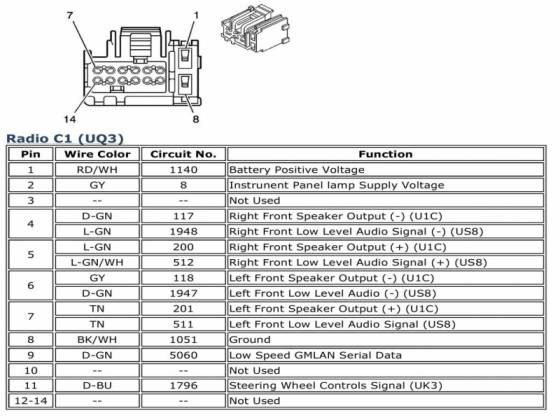
- Speaker Wires: These come in pairs for each speaker – one positive (+) and one negative (-). They're typically color-coded for easy identification (e.g., white/white-black for the left front speaker). Keep polarity in mind – reversing the speaker wires can negatively affect sound quality.
- Antenna Wire: This is a coaxial cable that connects the radio to the antenna, typically with a unique connector.
- Data Bus Wires: Newer vehicles use a CAN (Controller Area Network) bus for communication between different modules. The radio often interfaces with the CAN bus for features like steering wheel controls and vehicle speed-sensitive volume. These wires are typically twisted pairs and are very sensitive to damage.
- Steering Wheel Control Wires: If your Silverado has steering wheel audio controls, there will be dedicated wires that allow you to control the radio without taking your hands off the wheel.
- Amplifier Turn-On Wire (Remote Wire): If you're adding an aftermarket amplifier, this wire (often blue) tells the amp to turn on when the radio is powered.
- Reverse Wire: Sometimes the radio utilizes a reverse signal for features like backup cameras.
Understanding Symbols
A wiring diagram uses standardized symbols to represent different components and connections. Getting familiar with these symbols is key to deciphering the diagram:
- Lines: Lines represent wires. Thicker lines may indicate wires with higher current carrying capacity. Dashed lines often indicate shielded wires.
- Colors: Wires are color-coded. The diagram will have a key that explains what each color represents (e.g., RED = Red, BLU = Blue, GRN = Green, BLK = Black, WHT = White, YEL = Yellow). Knowing these color codes prevents you from accidentally connecting the wrong wires.
- Connectors: Connectors are represented by various shapes, such as circles, squares, or trapezoids. They indicate where wires are joined or disconnected.
- Ground Symbols: Typically shown as a series of horizontal lines decreasing in size, connected to a vertical line.
- Resistors: Represented by a zig-zag line.
- Capacitors: Represented by two parallel lines.
- Diodes: Represented by a triangle pointing to a line.
- Fuses: Represented by a squiggly line within a rectangle.
Pay attention to how the lines connect and intersect. A dot at the intersection indicates a connection. If lines cross without a dot, it means they are simply passing over each other and are not electrically connected.
How It Works: Signal Flow
The diagram shows the flow of electrical signals. It starts with the power source (battery), then goes to the radio through the power and ignition wires. The radio processes audio signals from various sources (antenna, CD player, USB) and sends amplified signals to the speakers. Data signals from the CAN bus control various radio functions. Think of it like a river: power flows from the source, gets channeled through different paths (wires), and ultimately powers the destination (speakers and other components).
For example, tracing the speaker wire path from the radio to the left front speaker will show you the wire color codes, any intermediate connectors, and the polarity of the speaker connection. Understanding this flow helps you pinpoint the source of any problem.
Real-World Use: Basic Troubleshooting
Let's say your radio suddenly stops working. Here's how the wiring diagram can help:
- Check the fuses: Locate the fuse box (usually under the dashboard or in the engine compartment). The diagram will show you which fuse protects the radio circuit. Use a multimeter to test the fuse for continuity. A blown fuse is a common cause of radio failure.
- Verify power and ground: Use a multimeter to check if the radio is receiving power (12V on the power and ignition wires) and has a good ground connection. If either is missing, trace the wiring back to the source to find the break.
- Inspect connectors: Check for loose or corroded connectors. Disconnect and reconnect them to ensure a good connection. Use electrical contact cleaner to remove any corrosion.
- Check speaker connections: If you only have sound from some speakers, check the speaker wires and connections.
Important: Always disconnect the battery's negative terminal before working on any electrical components to prevent shorts and shocks. When using a multimeter, be sure to set it to the correct voltage and current range to avoid damaging the meter or the vehicle's electrical system.
Safety Considerations
Working with automotive electrical systems can be dangerous. Here are some key safety precautions:
- Disconnect the battery: As mentioned earlier, this is the most important safety step.
- Avoid working on live circuits: If you must work on a live circuit, use extreme caution and wear insulated gloves.
- Be careful with the data bus wires: These wires are sensitive and can be easily damaged. Always use a proper wire stripper and crimper when working with them.
- Don't exceed the fuse rating: Replacing a blown fuse with a higher amperage fuse can overload the circuit and cause a fire.
- Proper Grounding: Grounding is essential for proper circuit operation and safety. Be sure all ground connections are clean, secure, and properly attached to the vehicle's chassis.
- Airbags: Be extremely careful when working near airbags, as accidental activation can cause serious injury. If you are unsure about how to safely work around airbags, consult a qualified technician.
The CAN bus is a high-speed data network that connects various electronic modules in the vehicle. Incorrect wiring or shorts on the CAN bus can cause serious problems with other vehicle systems. If you're unsure about how to work with the CAN bus, it's best to consult a qualified technician.
Always double-check your work before reconnecting the battery. A wiring diagram is only as good as your ability to read and understand it. Take your time, be meticulous, and don't be afraid to ask for help if you get stuck.
We have the complete 2014 Silverado radio wiring harness diagram available for download. It's a PDF file that you can print out and take with you to the garage. Having the right tools and information can make all the difference in getting the job done right! Good luck with your project!