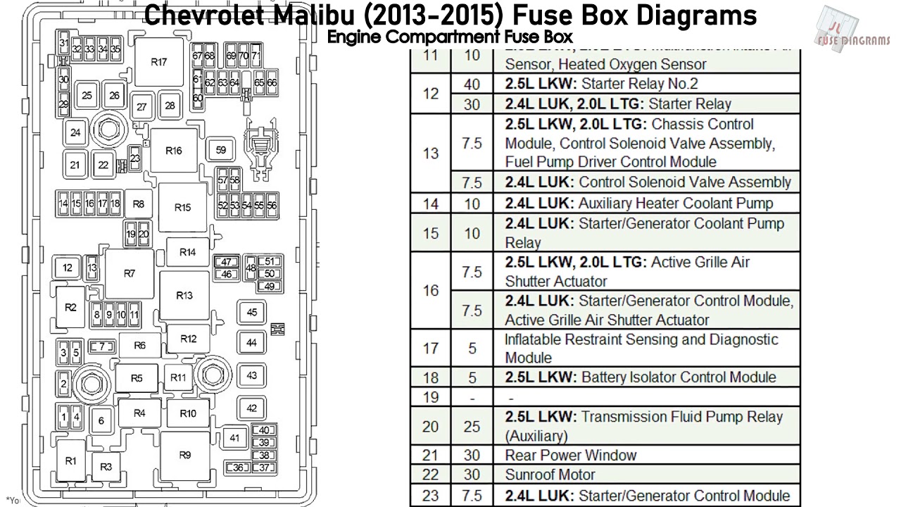
2015 Chevy Malibu Interior Fuse Box Diagram
So, you're diving into the electrical system of your 2015 Chevy Malibu, specifically the interior fuse box, huh? Smart move. Understanding this component is crucial for troubleshooting electrical issues, performing modifications, or simply gaining a deeper understanding of your car's inner workings. This article will serve as your guide to navigating the 2015 Malibu's interior fuse box diagram, assuming you've got some experience under the hood.
Why This Diagram Matters
The interior fuse box diagram is your roadmap to your car's electrical system. It's not just a pretty picture; it's essential for several reasons:
- Troubleshooting Electrical Problems: A blown fuse is often the first suspect when something electrical stops working. The diagram tells you which fuse controls which circuit.
- Modifications: Tapping into existing circuits for aftermarket accessories (like adding a dashcam or upgraded stereo) requires knowing which circuits are safe to use and what amperage they're rated for.
- Learning Your Car: Understanding the fuse box layout helps you understand how different electrical components are interconnected within your Malibu.
- Preventing Damage: Using the wrong amperage fuse or tampering with critical circuits can lead to serious electrical damage, even fire. The diagram helps you avoid these costly mistakes.
Key Specs and Main Parts of the Interior Fuse Box
The interior fuse box in the 2015 Chevy Malibu is typically located on the driver's side, often behind a small access panel near the dashboard or beneath the instrument panel. Here's a breakdown of its key components:
- Fuse Box Housing: The physical container that holds all the fuses and relays.
- Fuses: These are sacrificial components designed to protect circuits from overcurrent. They contain a thin wire that melts and breaks the circuit if the current exceeds a safe level. Fuses are rated in amperes (amps), which indicates the maximum current they can handle.
- Relays: Relays are electrically operated switches. They allow a low-current circuit to control a high-current circuit. For example, the headlight relay uses a small current from the headlight switch to control the much larger current needed to power the headlights.
- Fuse Diagram Label: Typically a sticker or card located inside the fuse box cover, showing the location and function of each fuse and relay. This is what we're dissecting!
- Test Points: Some fuse boxes have test points to easily check the voltage across a fuse without removing it.
Decoding the Fuse Diagram: Symbols, Lines, and Colors
The fuse diagram uses a standardized set of symbols, lines, and colors to convey information efficiently. Let's break down the most common elements:
- Fuse Symbols: Fuses are usually represented by a zigzag line inside a rectangle. Different diagrams might use slightly different variations, but the zigzag is the key identifier.
- Relay Symbols: Relays are typically represented by a coil symbol (a series of semicircles) and a switch symbol (a line connecting two points).
- Circuit Lines: Lines connect the fuse symbols to the components they protect. A thicker line usually indicates a higher current capacity.
- Color Coding: Fuses are color-coded according to their amperage rating. This is an industry standard. Common colors include:
- Yellow: 20 Amps
- Blue: 15 Amps
- Red: 10 Amps
- Brown: 7.5 Amps
- Orange: 5 Amps
- Clear/White: Can vary, often 25 or 30 Amps. Always check the number!
- Labels: Each fuse and relay will have a label indicating its function. These labels can be abbreviations or acronyms, so you might need to refer to your owner's manual or a service manual for clarification. Examples include "ECM" (Engine Control Module), "BCM" (Body Control Module), "IGN" (Ignition), "PWR WDO" (Power Windows), etc.
How It Works: From Fuse to Function
The fuse box acts as a central distribution point for electrical power. Power from the battery is routed to the fuse box, where it's distributed to various circuits throughout the car. Each circuit is protected by a fuse of the appropriate amperage rating. When a circuit experiences an overcurrent (e.g., due to a short circuit or a faulty component), the fuse blows, interrupting the flow of current and preventing damage to other components. Relays, as mentioned earlier, act as remotely controlled switches, allowing low-current circuits to control high-current devices.
Think of it like this: The battery is the power plant, the wires are the power lines, and the fuse box is a substation. The fuses are circuit breakers, protecting each branch of the power grid from overloads.
Real-World Use: Basic Troubleshooting Tips
Here's how to use the fuse diagram for basic troubleshooting:
- Identify the Problem: Determine which electrical component isn't working (e.g., the radio, a headlight, the power windows).
- Consult the Diagram: Locate the fuse or relay associated with that component in the fuse box diagram.
- Inspect the Fuse: Visually inspect the fuse. If the wire inside is broken or melted, the fuse is blown. You can also use a multimeter to test the fuse for continuity (resistance). A good fuse will have very low resistance.
- Replace the Fuse: Replace the blown fuse with a new fuse of the exact same amperage rating. Never use a fuse with a higher amperage rating; this could damage the circuit and potentially cause a fire.
- Test the Circuit: After replacing the fuse, test the component to see if it's working. If the fuse blows again immediately, there's likely a short circuit or other problem in the circuit that needs further investigation.
- Relay Troubleshooting: If the fuse is good but the component still doesn't work, the relay might be faulty. Relays can be tested using a multimeter and by swapping them with a known good relay (if available).
Safety First: Risky Components and Best Practices
Working with electrical systems involves inherent risks. Here are some safety precautions:
- Disconnect the Battery: Before working on any electrical components, disconnect the negative terminal of the battery. This prevents accidental shorts and electrical shocks.
- Use Proper Tools: Use insulated tools designed for automotive electrical work.
- Don't Exceed Amperage Ratings: Never use a fuse with a higher amperage rating than specified for the circuit.
- Be Careful with High-Current Circuits: Circuits like the starter motor and alternator carry very high currents. Avoid touching these components while the engine is running or the battery is connected.
- Avoid Water: Keep electrical components dry. Water can cause short circuits and corrosion.
- Airbags and SRS: Airbag circuits (SRS - Supplemental Restraint System) are extremely sensitive and can be dangerous to work on. Improper handling can cause the airbags to deploy unexpectedly. If you suspect a problem with the airbag system, consult a qualified technician.
This guide provides a solid foundation for understanding and using the 2015 Chevy Malibu's interior fuse box diagram. Remember to always consult your owner's manual or a service manual for specific details and procedures. And if you're ever unsure about something, don't hesitate to seek professional help.
We have the complete 2015 Chevy Malibu Interior Fuse Box Diagram available for download. This high-resolution file will provide you with all the necessary details to navigate your vehicle's electrical system effectively.