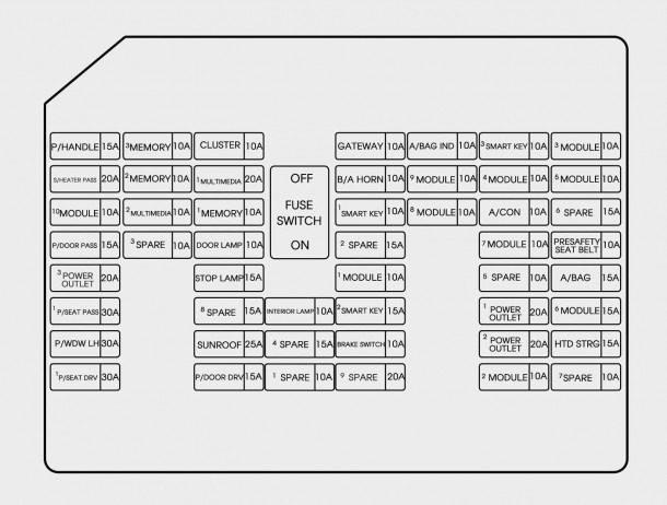
2015 Chrysler 200 Interior Fuse Box Diagram
For the experienced DIYer or modder tackling electrical projects on a 2015 Chrysler 200, understanding the interior fuse box diagram is absolutely critical. It's your roadmap to diagnosing electrical issues, safely tapping into circuits, or installing aftermarket accessories. Without it, you're essentially working blind, increasing the risk of damaging your vehicle's sensitive electrical system. This guide will demystify the 2015 Chrysler 200's interior fuse box, giving you the knowledge you need to troubleshoot problems and execute modifications with confidence.
Purpose of the Fuse Box Diagram
The fuse box diagram serves several vital purposes:
- Troubleshooting Electrical Problems: When an electrical component fails (e.g., a power window, cigarette lighter, or infotainment system), the fuse box diagram helps you quickly identify and check the relevant fuse.
- Locating Specific Circuits: If you're adding an aftermarket accessory like a dashcam or amplifier, the diagram shows you which circuits are available and suitable for tapping into.
- Preventing Overloads: Understanding fuse ratings allows you to avoid overloading circuits, which can lead to blown fuses or, in worst-case scenarios, electrical fires.
- General Understanding of Vehicle Electrical System: Even without immediate issues, studying the diagram provides valuable insight into how the various electrical components are interconnected.
Key Specs and Main Parts of the Interior Fuse Box
The interior fuse box in the 2015 Chrysler 200 is typically located in the driver's side footwell, behind a removable access panel. Access is usually quite straightforward but may require some contortion on your part to get a good view. The key specs to note are:
- Fuse Types: The 2015 Chrysler 200 uses a mix of fuse types, including blade fuses (ATO/ATC) and possibly mini-fuses. Blade fuses are the most common and are characterized by their flat, two-pronged design. They come in various sizes and amp ratings.
- Amp Ratings: Fuses are rated in Amperes (Amps or A), indicating the maximum current they can safely handle. Common ratings include 5A, 7.5A, 10A, 15A, 20A, 25A, and 30A. Using a fuse with a higher amp rating than specified can damage the circuit it's protecting.
- Fuse Box Cover: The cover is crucial as it often contains a simplified diagram of the fuse layout. However, the most detailed diagram is the one we'll be discussing and providing a link for download.
- Relays: While not strictly fuses, relays are often housed within the fuse box. Relays are electromechanical switches that control high-current circuits using a low-current signal. They're essential for controlling things like headlights, the fuel pump, and the starter motor.
Understanding Fuse Box Symbols and Layout
Fuse box diagrams use standardized symbols and a logical layout to represent the different components and circuits. Here's a breakdown:
- Lines: Solid lines typically represent direct electrical connections between components. Dashed lines may indicate connections through a harness connector or a shared ground.
- Colors: While not always present on the diagram itself, wire colors are crucial when tracing circuits in the vehicle. The wiring diagrams are separate from the fuse box diagram, but they are crucial for in-depth troubleshooting. Consult a wiring diagram to cross-reference fuse locations with wire colors.
- Icons: Icons represent the specific component protected by the fuse. Common icons include a lightbulb (for lights), a steering wheel (for power steering), a radio (for the infotainment system), and a fan (for the climate control system). These icons can vary slightly in appearance, but their meaning is generally intuitive.
- Fuse Numbers/Labels: Each fuse location is typically labeled with a number or a descriptive name (e.g., "Radio," "Cigar Lighter," "Power Windows"). This is how you identify the correct fuse on the diagram.
How the Fuse Box Works
The fuse box acts as a central distribution point for electrical power in your vehicle. Power from the battery is routed through the fuse box, and each circuit is protected by a fuse. When an excessive current flows through a circuit (due to a short circuit or an overload), the fuse's internal filament melts, breaking the circuit and preventing damage to the protected component. This is a simple but effective safety mechanism. It's absolutely crucial to replace a blown fuse with one of the exact same amp rating. Using a higher-rated fuse can bypass the protection and cause serious damage.
Relays, when present in the fuse box, act as remote switches. They allow a low-current signal (e.g., from a switch on the dashboard) to control a high-current circuit (e.g., the headlights). This prevents excessive current from flowing through the switch itself, which could damage it. The relay uses a small electromagnetic coil to open or close a set of contacts, completing or breaking the high-current circuit.
Real-World Use: Basic Troubleshooting
Here's how to use the fuse box diagram for basic troubleshooting:
- Identify the Problem: Determine which electrical component is not working (e.g., the windshield wipers).
- Consult the Diagram: Locate the fuse or relay associated with the malfunctioning component on the fuse box diagram.
- Inspect the Fuse: Visually inspect the fuse. If the filament is broken or blackened, the fuse is blown and needs to be replaced.
- Test the Fuse (Optional): For added certainty, use a multimeter to test the fuse's continuity. A working fuse will show continuity (a reading of near zero ohms).
- Replace the Fuse: Replace the blown fuse with a new fuse of the same amp rating.
- Test the Component: After replacing the fuse, test the malfunctioning component to see if it's now working.
- If the Fuse Blows Again: If the new fuse blows immediately or shortly after being replaced, it indicates a persistent short circuit or overload in the circuit. This requires further investigation and may necessitate the help of a qualified mechanic. Do not continue to replace the fuse. You are masking a more serious underlying issue.
Safety Precautions
Working with automotive electrical systems can be hazardous. Here are some essential safety precautions:
- Disconnect the Battery: Before working on the fuse box or any electrical components, disconnect the negative (black) terminal of the battery to prevent accidental short circuits.
- Use Insulated Tools: Use tools with insulated handles to prevent electric shock.
- Avoid Working in Wet Conditions: Never work on electrical systems in wet or damp conditions.
- Identify High-Current Circuits: Be extra cautious when working with high-current circuits, such as those for the starter motor, alternator, and headlights. These circuits can deliver a significant electrical shock.
- Never Bypass a Fuse: Never bypass a fuse by using a piece of wire or other conductive material. This eliminates the circuit protection and can lead to a fire.
- Consult a Professional: If you're not comfortable working with automotive electrical systems, consult a qualified mechanic. Electrical problems can be complex and require specialized knowledge and equipment.
The 2015 Chrysler 200's interior fuse box diagram is a valuable tool for any DIY mechanic. By understanding its layout, symbols, and function, you can diagnose electrical problems, install aftermarket accessories, and maintain your vehicle's electrical system safely and effectively. Remember to always prioritize safety and consult a professional if you're unsure about any aspect of the repair.
We have the complete, high-resolution 2015 Chrysler 200 Interior Fuse Box Diagram available for download. This detailed diagram will be an invaluable resource for your automotive projects. Click the link below to access the file.
[Link to download the 2015 Chrysler 200 Interior Fuse Box Diagram]