
2015 Ford Escape Coolant Hose Diagram
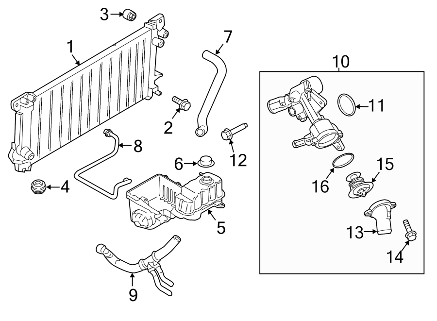
The 2015 Ford Escape, a popular compact SUV, relies on a complex cooling system to maintain optimal engine temperature. Understanding the coolant hose diagram is crucial for DIY mechanics, modders, and even experienced car owners who want to tackle cooling system repairs or modifications. This article provides a detailed breakdown of the 2015 Ford Escape's coolant hose diagram, explaining its components, function, and troubleshooting tips.
Purpose of the Coolant Hose Diagram
The coolant hose diagram is essentially a roadmap of the engine's cooling system. It illustrates the path coolant takes as it circulates through the engine, radiator, heater core, and other components. This diagram is essential for several reasons:
- Repair and Maintenance: Identifying and replacing damaged or leaking coolant hoses is a common maintenance task. The diagram helps you quickly locate the correct hose and understand its connections.
- Troubleshooting: Overheating or coolant leaks can be complex to diagnose. The diagram allows you to trace the coolant flow and pinpoint the source of the problem.
- Modifications: If you're modifying your Escape's engine or cooling system (e.g., adding an aftermarket intercooler), understanding the existing coolant hose layout is vital to ensure proper integration.
- Understanding System Operation: Even if you're not planning repairs, studying the diagram gives you a better understanding of how your engine's cooling system functions, which can aid in preventative maintenance.
Key Specs and Main Parts
The 2015 Ford Escape came with several engine options, including:
- 1.6L EcoBoost I4
- 2.0L EcoBoost I4
- 2.5L Duratec I4
While the general cooling system layout is similar across these engines, minor variations in hose routing might exist. Therefore, it's always recommended to consult the specific diagram for your engine type, which you can download at the end of this article. Some key components illustrated in the diagram include:
- Radiator: The primary heat exchanger, dissipating heat from the coolant to the atmosphere.
- Coolant Hoses: Flexible rubber or silicone hoses that transport coolant between components. These come in various sizes and shapes. The diagram will identify the inlet hose and outlet hose that connect the radiator to the engine.
- Thermostat: A valve that regulates coolant flow to maintain optimal engine temperature.
- Water Pump: A mechanically driven pump that circulates coolant through the system.
- Heater Core: A small radiator located inside the vehicle's cabin, providing heat to the interior.
- Expansion Tank (Coolant Reservoir): A reservoir that accommodates coolant expansion and contraction due to temperature changes.
- Coolant Temperature Sensor (CTS): Measures the coolant temperature and sends the information to the engine control unit (ECU).
- Bypass Hose: This hose allows coolant to circulate within the engine block when the thermostat is closed (engine is cold), ensuring even heating.
Symbols and Conventions in the Coolant Hose Diagram
Coolant hose diagrams use standard symbols and conventions to represent different components and fluid flow. Understanding these is key to interpreting the diagram correctly:
- Lines: Solid lines typically represent coolant hoses. Dashed lines might indicate vacuum lines or other auxiliary systems.
- Arrows: Arrows on the lines indicate the direction of coolant flow. This is crucial for understanding the coolant's circulation path.
- Colors: While not universally standardized, some diagrams use colors to differentiate between hot and cold coolant lines. Red might indicate hot coolant flowing away from the engine, while blue might indicate cooler coolant returning to the engine. Always refer to the diagram's legend to confirm the color coding.
- Component Symbols: Radiators, water pumps, thermostats, and other components are represented by simplified symbols. These symbols are usually labeled with abbreviations (e.g., "RAD" for radiator, "WP" for water pump).
- Clamps: Small circles or icons along the lines indicate hose clamps, which secure the hoses to their respective fittings.
How the Coolant System Works
The coolant system operates on a closed-loop principle. Here's a simplified explanation:
- The water pump circulates coolant through the engine block and cylinder head, absorbing heat generated by combustion.
- The heated coolant flows out of the engine and towards the thermostat.
- If the engine is cold, the thermostat remains closed, preventing coolant from flowing to the radiator. Instead, coolant is directed through a bypass hose, back to the water pump, allowing the engine to warm up quickly and evenly.
- Once the engine reaches its operating temperature, the thermostat opens, allowing coolant to flow to the radiator.
- In the radiator, the coolant's heat is dissipated to the atmosphere through fins and airflow.
- The cooled coolant then flows back to the water pump, completing the cycle.
- The heater core receives hot coolant diverted from the engine. A blower fan forces air across the heater core, warming the air and providing heat to the vehicle's interior.
- The expansion tank accommodates changes in coolant volume due to temperature fluctuations, preventing pressure buildup.
Real-World Use: Basic Troubleshooting Tips
Using the coolant hose diagram, you can perform basic troubleshooting:
- Coolant Leaks: Inspect all hoses, connections, and components shown in the diagram for signs of leaks (e.g., coolant stains, drips). Tighten hose clamps if necessary. If a hose is cracked or deteriorated, replace it.
- Overheating: Check the coolant level in the expansion tank. If low, add coolant. If the engine overheats repeatedly, use the diagram to trace the coolant flow and identify potential blockages or thermostat issues. Inspect the radiator for damage or debris buildup.
- No Heat: If the heater is not producing heat, check the coolant level and inspect the heater core hoses for blockages or leaks. A faulty thermostat can also prevent hot coolant from reaching the heater core.
Safety Considerations
Working with the cooling system involves several safety risks:
- Hot Coolant: Never open the radiator cap or coolant reservoir while the engine is hot. Coolant is under pressure and can cause severe burns. Allow the engine to cool completely before working on the system.
- Toxic Coolant: Coolant is toxic and should be handled with care. Avoid skin contact and ingestion. Clean up any spills immediately. Dispose of used coolant properly at a recycling center.
- High Pressure: The cooling system operates under pressure. Relieve the pressure by opening the radiator cap (when the engine is cool!) before disconnecting any hoses or components.
It is important to know that depending on the source of a leak it could be a relatively simple task to fix, or a far more complicated one. If you feel uncomfortable doing any repair, it is always advisable to take your car to a qualified mechanic.
We have the 2015 Ford Escape Coolant Hose Diagram available for download. This diagram will provide you with a visual representation of the system and make troubleshooting and repairs easier. Consult your specific engine type for accurate diagram.