
2015 Ford Escape Rear Suspension Diagram
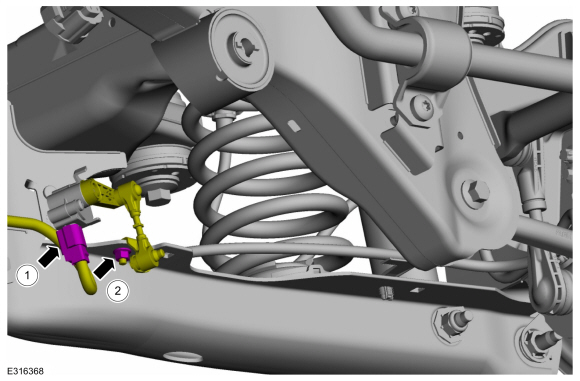
Let's dive into the rear suspension of the 2015 Ford Escape. Whether you're planning a repair, contemplating an upgrade, or simply want to understand how your vehicle handles, a solid grasp of the rear suspension is essential. This article will break down a typical diagram, focusing on the key components and how they interact, empowering you to tackle common issues and appreciate the engineering that keeps your Escape rolling smoothly.
Purpose of the Rear Suspension Diagram
A rear suspension diagram is your roadmap to understanding, diagnosing, and repairing the rear suspension system. It’s more than just a pretty picture; it’s a critical tool that allows you to:
- Identify components: Quickly locate specific parts for ordering or replacement.
- Understand assembly: Grasp the correct order and orientation of parts during reassembly.
- Troubleshoot issues: Trace potential problems based on symptom and component interaction.
- Plan modifications: Evaluate the impact of aftermarket components and ensure proper fitment.
- Learn the system: Develop a deeper understanding of suspension dynamics and vehicle handling.
Key Specs and Main Parts
The 2015 Ford Escape utilizes a fully independent, Control Blade Multilink rear suspension. This design offers a good balance of ride comfort and handling precision. Here's a breakdown of the key components:
- Control Arms (Upper and Lower): These are the main links that connect the wheel hub assembly to the vehicle's chassis. They control wheel movement in relation to the body. The upper control arm typically handles camber, while the lower control arm contributes to stability and absorbs impact.
- Trailing Arm: This arm, usually mounted longitudinally, helps control fore-aft movement of the wheel, providing stability during braking and acceleration.
- Wheel Hub/Bearing Assembly: This houses the wheel bearing and provides the mounting point for the wheel itself. It allows the wheel to rotate freely.
- Shock Absorber (Damper): The shock absorber, often called a damper, controls the rate of compression and rebound of the suspension, preventing excessive bouncing and improving ride quality.
- Coil Spring: The coil spring supports the weight of the vehicle and provides suspension travel. It works in conjunction with the shock absorber to absorb bumps and maintain ride height.
- Stabilizer Bar (Sway Bar): The stabilizer bar, also known as a sway bar or anti-roll bar, connects the left and right sides of the suspension. It resists body roll during cornering, improving handling.
- Knuckle (Upright): This component connects the control arms, hub assembly, and shock absorber. It acts as the central pivot point for the wheel assembly.
- Bushings: Made of rubber or polyurethane, bushings are inserted into the control arm mounting points to absorb vibrations and allow for controlled movement. Worn bushings contribute to noise and sloppy handling.
Understanding Suspension Diagram Symbols
Suspension diagrams often use specific symbols and conventions to represent components and their relationships. Here's a general guide to interpreting these markings:
- Lines:
- Solid Lines: Typically represent rigid components like control arms, struts, or the chassis itself.
- Dashed Lines: Often indicate hidden components or lines that are behind other parts.
- Dotted Lines: May represent movement paths or reference points.
- Colors: While color-coding varies, some common uses include:
- Red: High-stress components or areas requiring special attention.
- Blue: Hydraulic lines or fluid-related components.
- Green: Grounding points or electrical connections.
- Icons:
- Coil Spring Symbol: A coiled line indicating the presence of a coil spring.
- Shock Absorber Symbol: A vertical line with a small rectangle, representing the damper.
- Bolt/Nut Symbol: Indicates fastening points and torque specifications are often noted near these symbols.
- Arrows: Show direction of movement or force.
Note: Always refer to the specific legend accompanying the diagram for accurate interpretation. The conventions can vary slightly between manufacturers and even between different diagrams from the same manufacturer.
How It Works: The Control Blade Multilink Suspension
The multilink suspension is designed to provide independent control over wheel movement. Here's how it works on the 2015 Escape:
As the wheel encounters a bump, the suspension components articulate. The coil spring compresses, absorbing the impact. The shock absorber dampens the spring's motion, preventing excessive oscillations. The control arms guide the wheel's vertical movement while maintaining proper alignment. The trailing arm prevents wheel hop during acceleration and braking.
During cornering, the stabilizer bar comes into play. When one wheel moves upward relative to the other, the stabilizer bar twists, transferring some of the force to the opposite wheel. This reduces body roll and improves stability.
The key advantage of a multilink suspension is its ability to optimize various suspension parameters, such as camber, toe, and roll center, independently. This allows for a more refined ride and improved handling compared to simpler suspension designs.
Real-World Use: Basic Troubleshooting
Understanding the rear suspension diagram can greatly aid in troubleshooting common problems:
- Clunking Noises: Often caused by worn bushings in the control arms or trailing arm. Inspect the bushings for cracks or excessive play.
- Squeaking Noises: May indicate dry or worn bushings or a failing shock absorber. Lubricate the bushings and inspect the shock absorbers for leaks.
- Excessive Bouncing: A sign of worn shock absorbers. Replace the shock absorbers in pairs.
- Uneven Tire Wear: Can be caused by misaligned suspension components. Have the alignment checked and adjusted.
- Poor Handling: Could be due to a variety of issues, including worn bushings, damaged control arms, or a broken stabilizer bar link. A thorough inspection is required.
If you notice these issues, always start by visually inspecting all components. Look for signs of damage, wear, or corrosion. Use the diagram to identify the correct components and their locations.
Safety Considerations
Working on the rear suspension can be dangerous if proper precautions are not taken.
- Spring Compression: The coil spring is under significant tension. Never attempt to remove or disassemble the spring without using a proper spring compressor. Improper handling of a compressed spring can result in serious injury.
- Torque Specifications: Always use a torque wrench to tighten suspension fasteners to the manufacturer's specified torque. Overtightening can damage components, while undertightening can lead to failure.
- Wheel Chocks and Jack Stands: Always use wheel chocks to prevent the vehicle from rolling and jack stands to support the vehicle's weight. Never work under a vehicle supported only by a jack.
- Brake Lines: Be extremely careful when working near brake lines. Damaging a brake line can result in brake failure.
- Rust and Corrosion: Severely corroded suspension components can be weakened and may fail unexpectedly. Inspect components carefully and replace them if necessary.
Disclaimer: This information is for educational purposes only. Always consult a qualified mechanic if you are unsure about any aspect of suspension repair or maintenance.
With a firm understanding of the 2015 Ford Escape's rear suspension system, armed with the correct diagram, you are well-equipped to tackle repairs, modifications, and preventative maintenance. Remember to prioritize safety and consult a professional when needed.
We have the diagram file available. If you're looking for a detailed diagram of the 2015 Ford Escape's rear suspension, please let us know and we can provide a link for download.