2015 Ford F150 Blend Door Actuator Diagram
Let's dive into the blend door actuator system in your 2015 Ford F-150. If you're experiencing inconsistent temperatures from your vents – like cold air on one side and hot on the other – chances are your blend door actuator is the culprit. Understanding the system and having access to a detailed diagram can save you a significant amount of money in repair costs, and potentially improve your vehicle's comfort, or allow for modifications to the climate control system.
Purpose of the Blend Door Actuator Diagram
The blend door actuator diagram is essentially a roadmap for the HVAC (Heating, Ventilation, and Air Conditioning) system. It illustrates the electrical connections, components, and their relationship within the blend door control circuit. This is crucial for:
- Troubleshooting: Identifying faulty wiring, connectors, or components when you're facing heating or cooling issues.
- Repair: Pinpointing the exact location of the actuator and related parts for replacement.
- Understanding the System: Gaining a deeper understanding of how your truck's climate control works, which is especially useful if you're planning any modifications or upgrades.
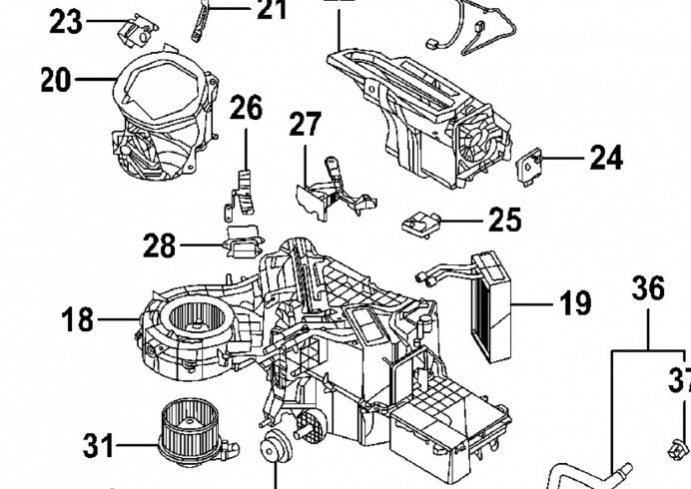
Key Specs and Main Parts of the 2015 F-150 Blend Door System
The 2015 F-150 uses a relatively straightforward blend door system, though it can vary slightly depending on whether you have manual or automatic climate control. Here’s a breakdown of the key components:
- Blend Door Actuator: This is the electromechanical device that physically moves the blend door. It's essentially a small motor connected to a gear train that controls the door's position. Often found behind the dashboard, the number of actuators will depend on climate control optioned.
- Blend Door: This is a flap or door inside the HVAC housing that regulates the mixture of hot and cold air flowing into the cabin. Its position determines the temperature of the air coming from the vents.
- HVAC Control Module: This is the "brain" of the system. It receives input from the temperature controls (dials or buttons) and sends signals to the blend door actuator to adjust the door's position.
- Temperature Sensors: These sensors (typically one inside the cabin and sometimes an ambient temperature sensor) provide feedback to the HVAC control module, allowing it to maintain the desired temperature.
- Wiring Harness and Connectors: These are the wires and connectors that connect all the components together. Corrosion or damage to these can cause intermittent or complete failure of the system.
Typical blend door actuators for this model year are controlled via Pulse Width Modulation (PWM) signals. PWM is a method of controlling the amount of power delivered to a device by varying the width of a pulse. In this case, the HVAC module uses PWM to precisely control the position of the blend door actuator.
Symbols and Diagram Interpretation
Understanding the symbols used in the blend door actuator diagram is essential for proper diagnosis. Here’s a general guide:
- Lines: Solid lines usually represent wires, while dashed lines might represent ground connections or shielded cables.
- Colors: Wire colors are typically indicated by abbreviations (e.g., "RD" for red, "BK" for black, "WH" for white). Refer to the diagram's key for specific color codes.
- Connectors: Connectors are usually represented by small rectangular or circular shapes. The diagram will show the connector's location and the wires that connect to it.
- Actuators: Actuators are shown as boxes with connecting lines showing electrical pinouts.
- Ground Symbols: Ground connections are typically represented by a series of horizontal lines decreasing in size.
- Component Symbols: Relays are displayed with a coil symbol, and switch contacts are usually displayed in an open and closed position.
Important: Always refer to the legend or key provided with the diagram. The exact symbols and color codes can vary slightly.
How It Works: A Deep Dive
The blend door actuator system operates based on a closed-loop feedback system. Here's how it works:
- User Input: You adjust the temperature setting on the HVAC controls.
- HVAC Module Processing: The HVAC control module receives the temperature setting and reads data from the temperature sensors.
- Signal Transmission: Based on the desired temperature and sensor readings, the HVAC module sends a PWM signal to the blend door actuator.
- Actuator Movement: The actuator receives the PWM signal and rotates the blend door to the appropriate position, mixing hot and cold air.
- Feedback Loop: Some actuators have a feedback potentiometer which sends an electrical resistance proportional to its position back to the HVAC Module. This helps the HVAC module accurately adjust the air temperature.
- Temperature Monitoring: The temperature sensors continue to monitor the cabin temperature, and the HVAC module adjusts the actuator's position as needed to maintain the desired temperature.
If any part of this system fails, the blend door might get stuck in one position, resulting in inconsistent or incorrect temperatures.
Real-World Use: Basic Troubleshooting Tips
Here are a few troubleshooting tips you can use with the diagram:
- No Heat or AC: Use the diagram to check the power supply and ground connections to the blend door actuator. A faulty fuse or a bad ground can prevent the actuator from working.
- Inconsistent Temperatures: Inspect the wiring and connectors for corrosion or damage. Also, try manually moving the blend door (if accessible) to see if it's physically stuck.
- Clicking Noise: A repetitive clicking noise from behind the dashboard often indicates a broken gear inside the blend door actuator. The diagram will help you locate and replace the actuator.
- Scan Tool: Use an OBD-II scan tool capable of reading HVAC codes. These codes can provide valuable clues about the specific problem area.
For example, a common code is B1081, which indicates a problem with the driver's side blend door actuator circuit. Use the wiring diagram to check the actuator connections, wiring, and the actuator itself.
Safety Considerations
Working on the electrical system of your vehicle can be dangerous. Always disconnect the negative battery cable before working on any electrical components. Be especially careful when probing electrical connectors with a multimeter or test light. Avoid piercing wires, as this can damage the insulation and lead to corrosion. If you're not comfortable working with electrical systems, it's best to consult a qualified mechanic.
Accessing the Diagram
We have a detailed blend door actuator diagram for the 2015 Ford F-150 available for download. This diagram includes all the necessary wiring information and component locations to help you diagnose and repair your truck's HVAC system. You can download the diagram to get started on your repair!
Remember to always consult your vehicle's service manual for specific procedures and torque specifications. Good luck!