2015 Ford Transit Ac Filler Line Location Diagram
If you're diving into the air conditioning system of your 2015 Ford Transit, understanding the location of the AC filler line (also known as the low-pressure service port) is crucial. This article provides a detailed explanation and a diagram to help you confidently diagnose, recharge, or perform other maintenance on your Transit's AC system. Having the right information not only saves you time and money but also ensures the safety and proper functioning of your vehicle.
Purpose of Understanding the AC Filler Line Location
Why is knowing the AC filler line location so important? There are several key reasons:
- Recharging the AC System: The low-pressure service port is where you connect your refrigerant charging equipment to add or adjust the refrigerant level in the system. This is a common maintenance task, especially in older vehicles where refrigerant leaks can occur over time.
- Diagnosing AC Problems: Connecting a manifold gauge set to the low and high-pressure ports allows you to read the system's pressures. These readings are vital for diagnosing problems such as a faulty compressor, a clogged expansion valve, or low refrigerant.
- Preventative Maintenance: Regularly checking the AC system pressures can help you identify potential issues before they become major problems, extending the life of your AC components.
- Learning and Understanding: For DIY enthusiasts, understanding the layout of the AC system enhances your overall automotive knowledge and allows you to perform more complex repairs in the future.
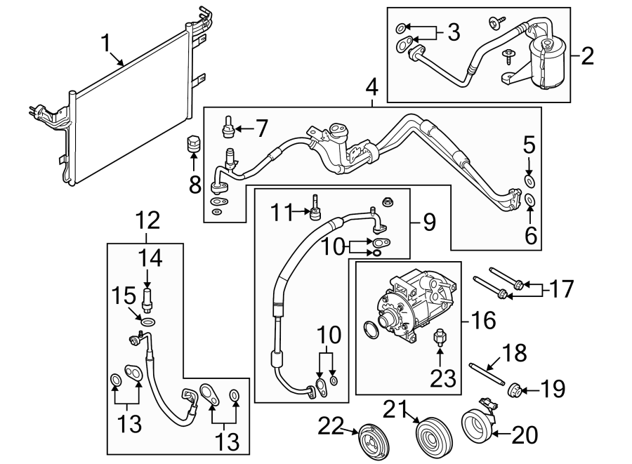
Key Specs and Main Parts of the 2015 Ford Transit AC System
Before we delve into the diagram, let's familiarize ourselves with the key components of the 2015 Ford Transit AC system:
- Compressor: The heart of the system, responsible for compressing the refrigerant and circulating it throughout the system.
- Condenser: Located in front of the radiator, the condenser dissipates heat from the compressed refrigerant, turning it into a high-pressure liquid.
- Receiver Drier (or Accumulator): This component filters out moisture and debris from the refrigerant. It also stores a small reserve of liquid refrigerant. The 2015 Transit is more likely to have an accumulator located on the low-pressure side.
- Expansion Valve (or Orifice Tube): Meters the flow of high-pressure liquid refrigerant into the evaporator, causing it to expand and cool.
- Evaporator: Located inside the dashboard, the evaporator absorbs heat from the cabin air, cooling the air that is blown into the passenger compartment.
- Refrigerant Lines: Hoses and tubes that carry the refrigerant between the various components. These lines have both high-pressure and low-pressure sections.
- Service Ports (High and Low Pressure): These ports allow access to the system for pressure testing and refrigerant charging. The filler line we are focusing on is the low-pressure service port.
For the 2015 Ford Transit, the refrigerant used is typically R-134a. It's crucial to verify the specific type recommended for your vehicle (usually found on a sticker under the hood) and use only that type.
Symbols, Lines, and Colors in the AC Diagram
An AC system diagram utilizes standard symbols and conventions to represent the various components and their connections. Here's a breakdown of common symbols:
- Solid Lines: Typically represent refrigerant lines, the actual hoses and tubes carrying the refrigerant.
- Dashed Lines: Often indicate electrical wiring or vacuum lines associated with the AC system's control and operation.
- Circles: Can represent various components, such as sensors, switches, or even connection points. The diagram key will define the exact meaning.
- Rectangles: Commonly used to represent larger components like the compressor, condenser, evaporator, and receiver drier.
- Arrows: Indicate the direction of refrigerant flow.
Colors are also often used to differentiate between high-pressure and low-pressure lines. While not universally standardized, red is frequently used for high-pressure lines, and blue for low-pressure lines. Always consult the diagram's legend for specific color coding.
How the AC System Works
Understanding the overall operation of the AC system helps in interpreting the diagram:
- The compressor compresses the refrigerant, increasing its pressure and temperature.
- The high-pressure, high-temperature refrigerant flows to the condenser, where it releases heat and transforms into a high-pressure liquid.
- The high-pressure liquid refrigerant passes through the receiver drier (or accumulator), where moisture and debris are removed.
- The refrigerant then flows to the expansion valve (or orifice tube), which meters the flow into the evaporator.
- As the refrigerant enters the evaporator, it expands and evaporates, absorbing heat from the air passing over the evaporator core. This cools the air blown into the cabin.
- The low-pressure, low-temperature refrigerant vapor returns to the compressor, completing the cycle.
Real-World Use and Basic Troubleshooting
Here's how you can use the diagram for troubleshooting common AC issues:
- Low Refrigerant: If your AC is blowing warm air, start by checking the refrigerant level using a manifold gauge set connected to the high and low-pressure service ports. The diagram will help you locate the low-pressure (filler) port. Low refrigerant is a common cause of poor AC performance.
- Compressor Issues: If the compressor isn't engaging, use the diagram to trace the electrical wiring to the compressor clutch to check for power. Also, check the AC relay and fuse in the power distribution box (fuse box).
- Clogged Condenser: Use the diagram to visually inspect the condenser for debris. A clogged condenser restricts airflow and reduces the system's cooling capacity.
- Leaking Components: With the system charged, you can use a UV dye and UV light (often sold in AC recharge kits) to locate leaks in lines, connections, or components shown in the diagram.
Safety Considerations
Working with AC systems involves inherent risks. The refrigerant is under high pressure and can cause frostbite if it comes into contact with your skin or eyes. Always wear safety glasses and gloves when working on the AC system.
- Refrigerant Exposure: Avoid direct contact with refrigerant. If refrigerant contacts your skin or eyes, flush immediately with water and seek medical attention.
- High Pressure: The system operates under high pressure. Never disconnect lines or components without first properly discharging the system. This is best left to a professional as improper discharge can release harmful refrigerant into the atmosphere.
- Electrical Components: Be cautious when working around electrical components. Disconnect the negative battery cable before working on any electrical parts of the AC system.
Disclaimer: This information is for educational purposes only and should not be substituted for professional advice. Always consult a qualified mechanic for complex AC repairs. Discharging refrigerant into the atmosphere is illegal and harmful to the environment. Ensure proper recovery and disposal of refrigerant.
Remember, proper diagnosis often requires specialized tools and expertise. If you're uncomfortable with any aspect of AC system repair, seek professional assistance.
We have the 2015 Ford Transit AC Filler Line Location Diagram available for download. Use it wisely and safely!