
2015 Jeep Cherokee Coolant Hose Diagram
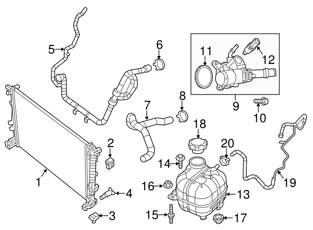
The 2015 Jeep Cherokee is a popular vehicle, and understanding its cooling system is crucial for its longevity and performance. One of the most important tools for diagnosing and repairing coolant leaks or cooling system malfunctions is the coolant hose diagram. This article serves as your comprehensive guide to understanding the 2015 Jeep Cherokee coolant hose diagram, enabling you to perform repairs and maintenance with greater confidence. We will explain the purpose, key specs, symbols, and real-world use of the diagram, ensuring you have the knowledge to troubleshoot cooling system issues effectively.
Purpose of the Coolant Hose Diagram
The coolant hose diagram is essentially a roadmap for your engine's cooling system. It illustrates the location of all coolant hoses, the direction of coolant flow, and the components involved in maintaining optimal engine temperature. It's invaluable for:
- Diagnosis: Pinpointing the source of coolant leaks. Coolant leaks can be messy and difficult to trace without a clear visual representation of the system.
- Repair: Replacing damaged or degraded hoses. The diagram shows you the correct routing for new hoses, ensuring proper installation.
- Maintenance: Performing routine checks of hose condition. Identifying potential weak points before they lead to a breakdown.
- Learning: Understanding the overall function and layout of the cooling system. This is crucial for more advanced diagnostics and modifications.
- Modifications: Planning and executing modifications to the cooling system, such as installing an aftermarket cooler or performance thermostat.
Without the diagram, you're essentially working blind. You risk misrouting hoses, damaging components, and ultimately, causing more harm than good. This is especially important on modern vehicles with complex engine bays.
Key Specs and Main Parts
The 2015 Jeep Cherokee, depending on the engine (2.4L Tigershark I4 or 3.2L Pentastar V6), will have a slightly different coolant hose configuration. However, the core components and principles remain the same. Let's outline the key parts:
- Radiator Hoses (Upper and Lower): These are the largest hoses in the system and connect the radiator to the engine. The upper hose carries hot coolant from the engine to the radiator, where it's cooled. The lower hose returns the cooled coolant to the engine.
- Heater Hoses: These hoses circulate coolant through the heater core, providing heat to the passenger cabin. Usually there are two - inlet and outlet.
- Bypass Hose: This hose allows coolant to circulate within the engine block when the thermostat is closed, ensuring even temperature distribution during engine warm-up.
- Radiator: The heat exchanger that dissipates heat from the coolant.
- Thermostat: A temperature-sensitive valve that regulates coolant flow to the radiator, maintaining optimal engine operating temperature. Its spec dictates when it opens (e.g., 195°F).
- Water Pump: A mechanical pump (typically driven by the serpentine belt) that circulates coolant throughout the system.
- Expansion Tank (Coolant Reservoir): A reservoir that accommodates coolant expansion and contraction due to temperature changes. It also acts as a low-coolant warning system.
- Hose Clamps: These secure the hoses to the various components. They can be spring clamps or screw-type clamps.
- Coolant Temperature Sensor (CTS): Measures the temperature of the coolant and sends the information to the Engine Control Unit (ECU).
When sourcing replacement hoses, always ensure you use the correct part number for your specific engine type. Using the wrong hose can lead to fitment issues, leaks, and even engine damage. The correct coolant type is also critical – usually a HOAT (Hybrid Organic Acid Technology) or OAT (Organic Acid Technology) formulation is recommended. Refer to your owner's manual for specific recommendations.
Symbols and Their Meaning
The coolant hose diagram isn't just a picture; it's a technical drawing with specific symbols. Understanding these symbols is key to interpreting the diagram correctly:
- Solid Lines: Represent coolant hoses. Thicker lines often indicate larger diameter hoses.
- Dashed Lines: May represent vacuum lines or other auxiliary lines indirectly related to the coolant system. Sometimes these can represent vent lines or overflow lines.
- Arrows: Indicate the direction of coolant flow. Follow the arrows to understand how the coolant circulates through the system.
- Color Coding: While not always present, some diagrams use color coding to distinguish between different types of hoses or sections of the cooling system. If present, a legend will explain the meaning of each color.
- Component Icons: Symbols represent components like the radiator, water pump, thermostat, and expansion tank. These are usually standardized and easily recognizable.
- Clamps: Small symbols often indicate the position of hose clamps.
Pay close attention to the direction of coolant flow indicated by the arrows. Incorrectly routing a hose can prevent proper cooling and lead to overheating. Familiarize yourself with the standard component icons to quickly identify parts within the diagram.
How It Works: The Cooling System in Action
The cooling system is designed to maintain optimal engine temperature, typically between 195°F and 220°F (90°C and 104°C). Here's a simplified overview of how it works:
- The water pump circulates coolant through the engine block and cylinder head, absorbing heat generated by combustion.
- Hot coolant flows through the upper radiator hose to the radiator.
- The radiator dissipates heat into the atmosphere via airflow.
- Cooled coolant exits the radiator through the lower radiator hose and returns to the engine.
- The thermostat regulates coolant flow to the radiator. When the engine is cold, the thermostat remains closed, allowing coolant to circulate only within the engine block via the bypass hose for faster warm-up. Once the engine reaches operating temperature, the thermostat opens, allowing coolant to flow to the radiator.
- The expansion tank accommodates coolant expansion and contraction, preventing pressure buildup and coolant loss.
- Heater hoses circulate coolant through the heater core to provide heat for the passenger compartment.
Understanding this flow is crucial for diagnosing cooling issues. For example, a cold radiator with an overheating engine could indicate a stuck-closed thermostat or a blockage in the upper radiator hose. A visual inspection using the coolant hose diagram makes pinpointing the problem much easier.
Real-World Use: Basic Troubleshooting Tips
Here are some common troubleshooting scenarios where the coolant hose diagram can be your best friend:
- Coolant Leak: Use the diagram to trace the source of the leak. Check hose connections, clamps, and the hoses themselves for cracks, bulges, or signs of deterioration. Remember to check areas where hoses contact other components, as chafing can cause leaks.
- Overheating: If your engine is overheating, use the diagram to check for restrictions in coolant flow. Inspect the radiator hoses for collapsing or kinking. Verify that the thermostat is opening properly.
- No Heat in Cabin: Check the heater hoses for blockages or kinks. Ensure that the heater control valve (if equipped) is functioning correctly. Use the diagram to trace the flow of coolant to the heater core.
- Coolant Loss: Inspect all hoses, connections, and the radiator for leaks. Check the expansion tank for cracks or damage. A pressure test of the cooling system can help locate hidden leaks.
- Hose Replacement: When replacing hoses, use the diagram to ensure proper routing. Make sure the hoses are not twisted or rubbing against other components. Always use new hose clamps and tighten them to the correct torque specification.
Remember that preventative maintenance is key. Regularly inspect your coolant hoses for signs of wear and tear. Replace hoses proactively before they fail. This can save you from costly repairs and potential breakdowns.
Safety Considerations
Working on the cooling system involves inherent risks. Here are some important safety precautions:
- Hot Coolant: Never remove the radiator cap or any coolant hose while the engine is hot. Coolant is under pressure and can cause severe burns. Allow the engine to cool completely before working on the cooling system.
- Pressure Release: Even when cool, there may still be residual pressure in the system. Slowly and carefully release the pressure by opening the expansion tank cap slightly before removing any hoses.
- Eye Protection: Always wear safety glasses to protect your eyes from coolant splashes.
- Gloves: Wear gloves to protect your hands from coolant, which can be irritating to the skin.
- Electrical Components: Be mindful of nearby electrical components, especially when working around the coolant temperature sensor. Avoid splashing coolant on electrical connectors.
- Sharp Objects: Use caution when using tools to remove hose clamps or disconnect hoses. Avoid damaging other components.
The radiator, thermostat housing, and water pump are all locations where hot coolant can be readily released. Extra caution is required when working on these components. If you are uncomfortable with any aspect of working on the cooling system, it's always best to consult a qualified mechanic.
Now that you have a deeper understanding of the 2015 Jeep Cherokee coolant hose diagram, you're better equipped to diagnose and repair cooling system issues. This knowledge can save you time and money, and keep your Jeep running smoothly for years to come.
We have the full resolution coolant hose diagram file available for download to assist you with your repairs, simply follow the link provided [hypothetical download link]. Remember to always consult your vehicle's repair manual for specific torque specifications and procedures.