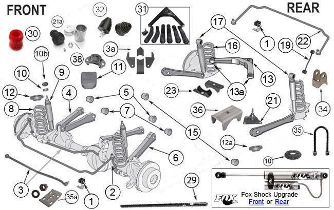
2015 Jeep Grand Cherokee Front Suspension Diagram
Understanding the front suspension of your 2015 Jeep Grand Cherokee can be incredibly valuable, whether you're tackling a simple repair, planning an upgrade, or simply want to learn more about how your vehicle works. This article provides a detailed overview of the front suspension diagram, highlighting key components, their functions, and basic troubleshooting techniques. Knowing this information will empower you to diagnose issues, perform basic maintenance, and make informed decisions about repairs.
Purpose of the Front Suspension Diagram
A front suspension diagram is more than just a visual aid; it's a roadmap to understanding the complex network of parts that connect your vehicle's frame to its front wheels. Its primary purposes include:
- Repair and Maintenance: Identifying the exact location of parts, their relationship to each other, and proper assembly order.
- Troubleshooting: Tracing potential problems by understanding the system's layout and how failures in one area can affect others.
- Upgrades and Modifications: Planning and executing modifications, like lift kits or performance upgrades, by providing the necessary dimensional and spatial information.
- Learning and Understanding: Gaining a deeper knowledge of automotive engineering principles and how various components interact to provide a smooth and controlled ride.
Key Specs and Main Parts
The 2015 Jeep Grand Cherokee typically utilizes an independent front suspension, specifically a short-and-long arm (SLA) or double-wishbone design. This design offers a good balance of ride comfort, handling, and off-road capability.
Main Parts:
- Upper Control Arm: Connects the upper portion of the steering knuckle to the vehicle's frame. Its main job is to control the camber angle of the wheel throughout suspension travel.
- Lower Control Arm: Connects the lower portion of the steering knuckle to the vehicle's frame. This is usually the larger and more robust of the two control arms as it handles more significant loads.
- Steering Knuckle (or Spindle): A pivoting component that houses the wheel hub and bearings and connects to the control arms and steering linkage.
- Wheel Hub and Bearings: Allows the wheel to rotate smoothly and supports the vehicle's weight.
- Shock Absorber (Damper): Dampens oscillations and controls the rate of suspension movement, preventing excessive bouncing.
- Coil Spring: Supports the vehicle's weight and provides resistance against compression, absorbing bumps and irregularities in the road. In some configurations, the coil spring may be separate from the shock absorber.
- Strut Assembly (if applicable): Combines the shock absorber and coil spring into a single unit. Some Grand Cherokees may use a traditional shock and spring setup, while others use a strut assembly.
- Sway Bar (Stabilizer Bar): Connects the left and right sides of the suspension and resists body roll during cornering. It's attached to the suspension via sway bar links.
- Sway Bar Links: Connect the sway bar to the control arms or struts.
- Tie Rods (Inner and Outer): Part of the steering linkage, connecting the steering rack to the steering knuckle, allowing steering input to turn the wheels.
- Ball Joints: Allow pivoting movement between the control arms and the steering knuckle. There are upper and lower ball joints.
- Bushings: Rubber or polyurethane components that cushion and dampen vibrations where suspension parts connect to the frame or other components.
Symbols and Conventions
Understanding the symbols used in a suspension diagram is crucial for accurate interpretation.
- Solid Lines: Typically represent rigid components like control arms, tie rods, and the steering knuckle.
- Dashed Lines: May indicate hidden parts, reference points, or lines of action (e.g., the axis of rotation).
- Colors: While color coding can vary depending on the diagram, common conventions include:
- Blue: Hydraulic lines (e.g., power steering).
- Red: High-stress components or areas of concern.
- Black: General structural components.
- Arrows: Indicate direction of movement, force, or flow.
- Labels and Annotations: Clearly identify each component and often include part numbers, torque specifications, or other relevant information.
How It Works
The front suspension's primary function is to isolate the vehicle's cabin from road imperfections and maintain tire contact with the road surface. Here's a simplified explanation of how the SLA/double-wishbone system achieves this:
- When the wheel encounters a bump, the suspension compresses, causing the coil spring (or torsion bar, depending on the specific configuration) to absorb the energy.
- The shock absorber dampens the oscillations of the spring, preventing the vehicle from bouncing excessively.
- The control arms allow the wheel to move vertically while maintaining a relatively constant camber angle, which is crucial for optimal tire contact and handling.
- The sway bar resists body roll during cornering by transferring some of the suspension load from the outside wheel to the inside wheel.
- The steering linkage (tie rods) translates the driver's steering input into wheel movement, allowing for precise control of the vehicle's direction.
Real-World Use - Basic Troubleshooting
A front suspension diagram can be invaluable for troubleshooting common issues:
- Clunking or Rattling Noises: Could indicate worn ball joints, bushings, sway bar links, or loose components. Inspect the diagram to identify potential sources of the noise and then visually inspect the corresponding parts on the vehicle.
- Excessive Bouncing or Poor Ride Quality: May be caused by worn shock absorbers or damaged springs. The diagram will show the location and connection points of these components.
- Uneven Tire Wear: Can be a sign of misalignment, worn ball joints, or damaged control arms. Use the diagram to understand how these components affect wheel alignment.
- Steering Issues (e.g., play, looseness): Could indicate worn tie rod ends or a problem with the steering rack. The diagram will illustrate the steering linkage and its connection to the steering knuckle.
Safety Considerations
Working on the front suspension involves significant safety risks. Always take the following precautions:
- Vehicle Stability: Ensure the vehicle is properly supported on jack stands on a level surface before working underneath. Never rely solely on a jack.
- Spring Compression: Coil springs store a tremendous amount of energy and can be extremely dangerous if released improperly. If you need to remove a spring, use a proper spring compressor and follow the manufacturer's instructions carefully. This is a critical safety point!
- Torque Specifications: Always tighten fasteners to the manufacturer's specified torque values. Over-tightening can damage components, while under-tightening can lead to loosening and failure. Refer to a repair manual for these values.
- Eye Protection: Wear safety glasses to protect your eyes from debris.
- Disconnect Battery: Disconnect the negative battery terminal before starting any electrical work.
- Ball Joints and Steering Components: Use appropriate tools, such as a ball joint separator, to safely disconnect these components. Avoid using excessive force, which can damage them.
The front suspension is a critical safety system. If you are not comfortable working on it, it's best to consult a qualified mechanic. Improper repairs can lead to serious accidents.
We have a detailed, high-resolution diagram of the 2015 Jeep Grand Cherokee front suspension available for download. This diagram provides a comprehensive visual representation of all the components and their relationships. This detailed diagram will be invaluable for understanding your Jeep's front suspension and aiding in any repair or modification work you undertake.