2015 Jeep Wrangler Front Suspension Diagram
Alright, let's dive into the 2015 Jeep Wrangler JK front suspension. Understanding this system is crucial whether you're planning routine maintenance, tackling some serious off-roading mods, or just want to grasp how your Jeep handles. This isn't just about replacing parts; it’s about comprehending the interplay of components to keep your ride smooth and safe. And to help you out, we’ve got the actual diagram available for download – more on that later.
Purpose of Understanding the Front Suspension Diagram
Why bother with a diagram? Simple: it's your roadmap to understanding, diagnosing, and repairing your Jeep's front suspension. A good diagram makes it far easier to identify components, understand their relationships, and plan your work. Here’s how it helps:
- Troubleshooting: Spotting wear and tear, leaks, or damage becomes significantly easier.
- Repairs: Knowing the location and function of each part streamlines the repair process, reducing errors.
- Modifications: Planning lift kits, new shocks, or other upgrades requires a solid grasp of the existing setup.
- Learning: Deepening your understanding of automotive engineering and mechanics.
Key Specs and Main Parts of the 2015 Jeep Wrangler JK Front Suspension
The 2015 Wrangler JK utilizes a high pinion Dana 30 or Dana 44 solid front axle, depending on the model. The axle is located by a five-link suspension system. Let's break down the main components:
Core Components:
- Solid Front Axle: This is a rigid beam connecting the front wheels. It houses the differential and axle shafts. Dana 30 axles were standard, while Dana 44 axles offered greater strength and came on Rubicon models.
- Coil Springs: These provide the main suspension support, absorbing bumps and maintaining ride height.
- Shock Absorbers (Dampers): These control the movement of the springs, preventing excessive bouncing. They dampen oscillations to provide a smoother ride.
- Upper and Lower Control Arms: These arms (two upper, two lower) connect the axle to the frame. They control axle movement and maintain proper alignment. They are crucial for caster and pinion angle.
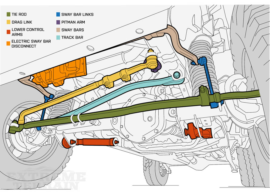
- Track Bar (Panhard Rod): This bar locates the axle laterally, preventing side-to-side movement. Its length and mounting points influence the axle's position relative to the vehicle's frame.
- Sway Bar (Anti-Roll Bar): This bar connects the two sides of the suspension, reducing body roll during cornering. It's designed to limit independent suspension movement, improving stability. Wranglers often have disconnects for off-road use, allowing greater articulation.
- Sway Bar Links: These connect the sway bar to the axle.
- Steering Knuckles (Spindles): These connect the wheels to the axle and allow for steering.
- Ball Joints: These allow the steering knuckle to pivot, enabling steering. They're a wear item and require periodic inspection.
Steering System Integration:
- Steering Gearbox: This translates steering wheel input into lateral movement to control the wheels.
- Drag Link: This connects the steering gearbox to the passenger side steering knuckle.
- Tie Rod: This connects the two steering knuckles, ensuring both wheels turn in unison.
Symbols and Conventions in Suspension Diagrams
Understanding the symbols used in the diagram is key to interpreting it correctly. While specific diagrams might vary slightly, some common conventions apply:
- Solid Lines: Generally represent rigid components like control arms, axles, and frame members.
- Dashed Lines: Often indicate hidden components or lines of influence (e.g., the path of motion).
- Circles and Dots: Represent joints or connection points, such as ball joints or bushings.
- Arrows: Indicate direction of movement or force.
- Labels: These clearly identify each component. Pay attention to abbreviations and part numbers.
- Colors: While not always present, some diagrams use color to differentiate between different systems or materials.
How the 2015 Jeep Wrangler JK Front Suspension Works
The front suspension of the 2015 JK is designed for both on-road comfort and off-road capability. Here’s the basic operation:
- Impact Absorption: When the wheels encounter a bump, the coil springs compress, absorbing the energy.
- Damping: The shock absorbers then dampen the spring's oscillation, preventing the vehicle from bouncing excessively.
- Axle Location: The control arms keep the axle properly located underneath the vehicle, controlling its movement. They maintain the correct geometry throughout the suspension's travel.
- Lateral Stability: The track bar prevents the axle from shifting sideways.
- Steering: The steering gearbox translates steering wheel input into motion, which is then transferred through the drag link and tie rod to steer the wheels.
- Roll Mitigation: The sway bar resists body roll during cornering.
Real-World Use and Basic Troubleshooting
Here are some common issues and how the diagram can help you diagnose them:
- Clunking Noises: Often indicate worn-out bushings in the control arms, track bar, or sway bar links. The diagram shows you where these bushings are located for inspection.
- Wandering Steering: Can be caused by worn ball joints, tie rod ends, or a loose track bar. The diagram helps you pinpoint these components for inspection.
- Uneven Tire Wear: Can result from misaligned suspension components. The diagram helps you understand how adjustments to control arms and track bar affect alignment angles.
- Excessive Body Roll: Could indicate a broken or disconnected sway bar or worn sway bar links.
When troubleshooting, always visually inspect the components identified in the diagram for damage, wear, or looseness.
Safety Considerations
Working on suspension components can be dangerous due to the stored energy in the springs and the potential for sudden movement. Here are some crucial safety tips:
- Spring Compression: Never attempt to remove or disassemble a coil spring without using a proper spring compressor. Improper spring compression can result in serious injury or death.
- Support: Always use jack stands to support the vehicle securely before working underneath it. Never rely solely on a jack.
- Torque Specs: Always tighten fasteners to the specified torque values. Loose fasteners can lead to component failure and accidents. Consult a repair manual for the correct torque specifications.
- Disconnect Battery: Disconnect the negative battery cable before working on any electrical components.
- Brake Lines: Be extremely careful not to damage brake lines. Damaged brake lines can result in brake failure.
- Wear appropriate PPE: Safety glasses, gloves and appropriate clothing.
Components under high stress, such as the coil springs, ball joints, and steering linkages, should be treated with extra caution. Always inspect these components thoroughly for signs of wear or damage before performing any repairs.
By understanding the 2015 Jeep Wrangler JK front suspension diagram and following these guidelines, you'll be well-equipped to tackle various maintenance and repair tasks safely and effectively. Remember, if you’re ever unsure about a procedure, consult a qualified mechanic.
And as promised, we've got the 2015 Jeep Wrangler JK front suspension diagram ready for you to download. It will certainly help you on your troubleshooting. [Link to Diagram Download Here]