2015 Nissan Pathfinder Alternator Wiring Diagram
Alright, let's dive into the 2015 Nissan Pathfinder alternator wiring diagram. Whether you're facing a charging issue, planning an electrical upgrade, or just wanting to understand your vehicle better, a solid grasp of this diagram is crucial. Think of it as the roadmap to your Pathfinder's electrical heart. We'll break down the components, the symbols, and how it all works together. Plus, we'll give you some practical troubleshooting tips. By the end, you'll be equipped to tackle alternator-related issues with confidence.
Purpose of Understanding the Alternator Wiring Diagram
Why bother with a wiring diagram in the first place? Simple: repairs, diagnostics, and modifications. If your Pathfinder's battery is constantly dying or you suspect alternator problems, the diagram provides the exact pathways electricity takes. This allows you to pinpoint shorts, opens, or other issues. Furthermore, if you're adding auxiliary lighting, a high-powered audio system, or any other electrical accessory, understanding the alternator's capabilities and wiring is vital to avoid overloading the system. It's the foundation for any electrical work on your vehicle.
Key Specs and Main Parts of the 2015 Pathfinder Alternator Circuit
Before we jump into the diagram itself, let's identify the critical components. The alternator is the star of the show, responsible for generating electricity to charge the battery and power the vehicle's electrical systems while the engine is running. Let's review the major components and specs:
- Alternator: The main electrical power generator. A typical 2015 Pathfinder alternator outputs between 13.5 and 14.8 volts.
- Battery: Stores electrical energy and provides power to start the engine. Typically a 12V battery.
- Voltage Regulator: Maintains a stable voltage output from the alternator, preventing overcharging. Could be internal or external to the alternator, depending on the specific model. The 2015 Pathfinder typically has an internal voltage regulator.
- Fusible Link/Fuse: A safety device that protects the electrical system from overcurrent. The main alternator fuse is often a high-amperage fuse (e.g., 120A-140A) in the engine compartment fuse box.
- Wiring Harness: A collection of wires bundled together to connect the various components.
- Connectors: Used to connect the wires to the components. Important to check for corrosion and secure connections.
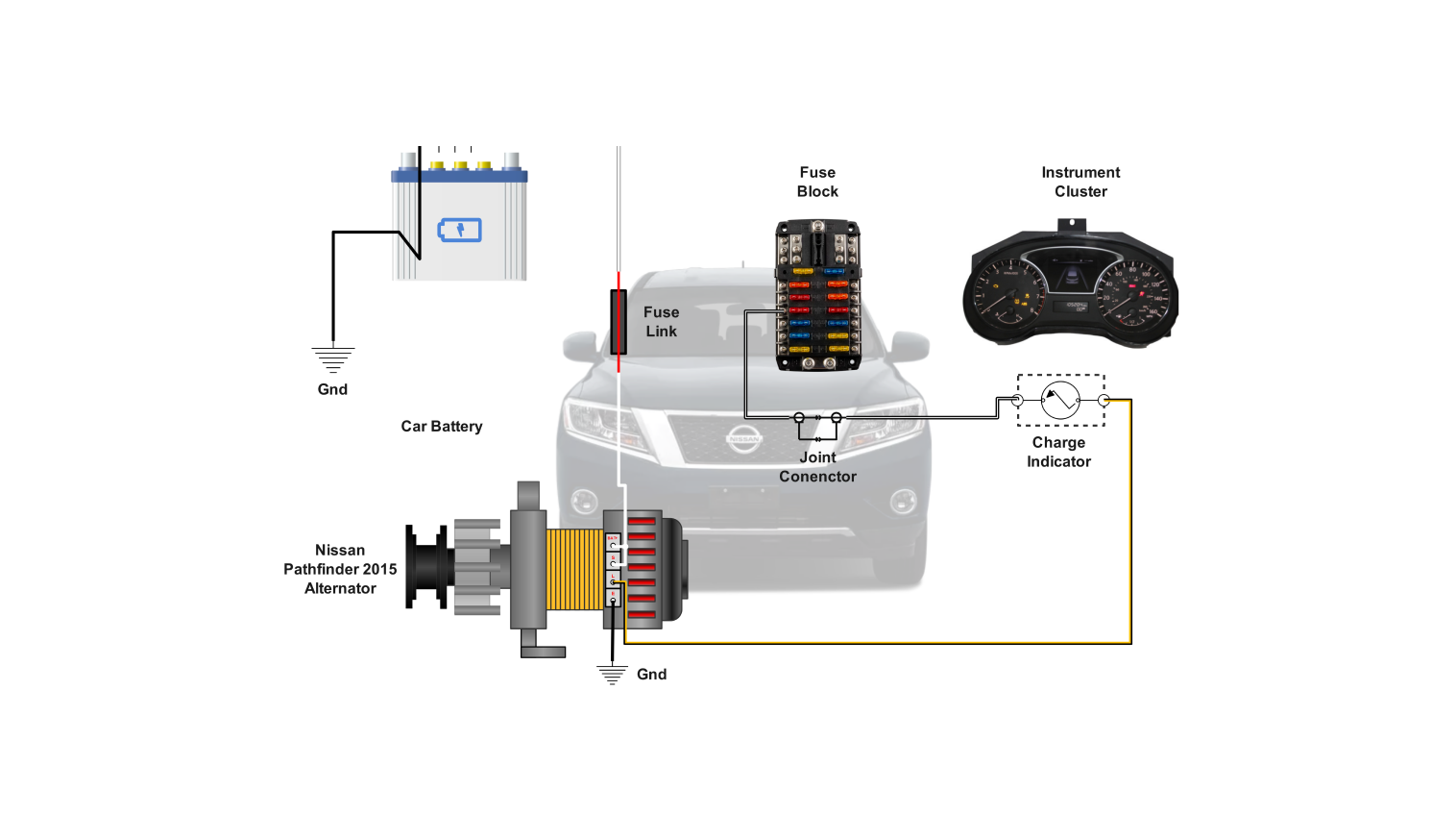
The key components of the alternator circuit are the alternator itself, the battery, the voltage regulator, and the wiring that connects them. You'll often find a large-gauge wire (usually red or orange) running directly from the alternator's output terminal to the positive (+) terminal of the battery. This is the main charging wire. There's also usually a smaller wire (often with a connector) that connects to the vehicle's computer (ECU or ECM) for voltage monitoring and control. And, of course, the alternator case is grounded to the engine block.
Decoding the Wiring Diagram: Symbols, Lines, and Colors
Now, let's decipher the wiring diagram's language. Wiring diagrams use standardized symbols to represent electrical components. Here's a quick rundown:
- Solid Lines: Represent wires. The thickness can sometimes indicate wire gauge (thicker lines = larger gauge).
- Dashed Lines: Often represent shielding or connections that are not direct wires.
- Circles: Can represent various things, depending on what's inside - a lamp, a sensor etc.
- Rectangles: Typically represent components like relays, fuses, or switches.
- Ground Symbol: Looks like a downward-pointing tree, indicating a connection to the vehicle's chassis ground.
Color coding is also crucial. While colors can vary slightly, some common conventions exist:
- Red: Usually indicates a positive (+) voltage supply.
- Black: Typically represents ground (-).
- Blue, Green, Yellow, White: Used for various signals and control wires. The diagram's legend will specify the function of each colored wire.
Understanding these symbols and color codes allows you to trace the flow of electricity through the circuit. Look for annotations near the wires and components. These often describe the wire gauge (e.g., 12 AWG), the component's function (e.g., "Alternator Output"), and the connector pin numbers.
How the 2015 Pathfinder Alternator Circuit Works
The alternator's job is to convert mechanical energy from the engine into electrical energy. It's driven by a belt connected to the engine's crankshaft. Inside the alternator, a rotating magnetic field induces a voltage in a set of stator windings. This voltage is then rectified (converted from AC to DC) and regulated by the voltage regulator. Here's the step-by-step:
- The engine starts, turning the alternator's pulley via the serpentine belt.
- The alternator begins to spin, creating AC (Alternating Current) electricity.
- The rectifier converts the AC electricity to DC (Direct Current) electricity.
- The voltage regulator monitors the battery's voltage and adjusts the alternator's output to maintain a stable charging voltage (around 13.5-14.8 volts).
- The alternator sends power to the battery to keep it charged and also powers the vehicle's electrical systems (lights, radio, etc.).
- The ECU (Engine Control Unit) monitors the alternator's performance through a feedback signal and may adjust engine parameters to optimize charging.
The voltage regulator is critical. Without it, the alternator would overcharge the battery, potentially damaging it and other electrical components. The regulator senses the battery's voltage and adjusts the alternator's output accordingly.
Real-World Use: Basic Troubleshooting Tips
So, your Pathfinder's battery keeps dying, or the battery light is on? Here's how to use the wiring diagram for basic troubleshooting:
- Visual Inspection: Start by visually inspecting the alternator, battery terminals, and wiring for any obvious signs of damage, corrosion, or loose connections.
- Voltage Measurement: Use a multimeter to measure the voltage at the battery terminals with the engine running. It should be between 13.5 and 14.8 volts. If it's significantly lower (e.g., below 12.5 volts), the alternator may not be charging properly.
- Continuity Test: Use the diagram to identify the main charging wire between the alternator and the battery. Disconnect the battery and use a multimeter to check the continuity of this wire. A lack of continuity indicates a break in the wire.
- Ground Check: Ensure the alternator is properly grounded to the engine block. Check the resistance between the alternator case and the engine block. It should be close to zero ohms.
- Fuse Check: Locate the alternator fuse (usually a high-amperage fuse in the engine compartment fuse box) and check its condition. Replace it if it's blown.
Remember to consult the wiring diagram to pinpoint the exact location of wires, connectors, and fuses. A digital multimeter is your best friend in this process. Also, consider using a scan tool to read out the error code; it can give you an idea about the cause. For example, P0562 means system voltage low, P0620 means alternator control circuit malfunction.
Safety First: Handling Risky Components
Working with electrical systems can be dangerous. Here are some critical safety precautions:
- Disconnect the Battery: Always disconnect the negative (-) battery cable before working on any electrical components. This prevents accidental shorts and shocks.
- High-Amperage Circuits: The alternator and battery circuits carry high currents. Be extremely careful when working with these components. Accidental shorts can cause sparks, fires, and burns.
- Proper Tools: Use insulated tools to avoid electrical shocks.
- Wear Safety Glasses: Protect your eyes from sparks and debris.
- Consult a Professional: If you're not comfortable working with electrical systems, consult a qualified mechanic.
The alternator's output terminal is a particularly high-risk area. Accidental contact with this terminal while the engine is running can result in a severe shock and damage to the vehicle's electrical system.
With this information, you should be better equipped to tackle any 2015 Nissan Pathfinder alternator wiring issue. Remember to take your time, double-check your work, and prioritize safety.
And, as promised, we have the full 2015 Nissan Pathfinder alternator wiring diagram file ready for you to download. Good luck with your repairs!