2015 Nissan Pathfinder Parts Diagram
The 2015 Nissan Pathfinder is a popular SUV known for its reliability and versatility. Whether you're tackling a minor repair, undertaking a significant modification, or simply trying to understand the inner workings of your vehicle, a parts diagram is an invaluable resource. This article will serve as a comprehensive guide to understanding the 2015 Nissan Pathfinder parts diagram, focusing on its purpose, key components, symbols, how it works, real-world applications, and critical safety considerations.
Purpose of a 2015 Nissan Pathfinder Parts Diagram
Why is a parts diagram so important? The primary purpose of a parts diagram is to provide a detailed, exploded view of the various systems and components within your vehicle. This allows you to:
- Identify Specific Parts: Quickly locate and identify the exact part you need for repair or replacement. Knowing the precise name and part number is crucial when ordering replacements.
- Understand Assembly: See how parts fit together and the order in which they should be assembled. This is particularly helpful when reassembling components after a repair.
- Troubleshoot Issues: By visualizing the relationships between different parts, you can better understand how a system operates and where potential problems might lie.
- Order Correct Parts: Eliminate guesswork when ordering parts. The diagram provides the necessary information to ensure you order the correct component for your specific model year and trim level.
- Plan Modifications: If you're planning any modifications or upgrades, the diagram can help you assess the feasibility of your project and identify any potential compatibility issues.
Key Specs and Main Parts of the 2015 Nissan Pathfinder
The 2015 Nissan Pathfinder is primarily equipped with a 3.5-liter V6 engine (VQ35DE). This engine delivers around 260 horsepower and 240 lb-ft of torque, and it's paired with a continuously variable transmission (CVT). Key systems highlighted in the parts diagram typically include:
Engine Components:
Engine Block: The core of the engine, housing the cylinders and other critical components.
Cylinder Head: Sits atop the engine block, containing the valves, camshaft(s), and spark plugs.
Pistons: Reciprocating components within the cylinders that convert combustion energy into mechanical energy.
Connecting Rods: Connect the pistons to the crankshaft.
Crankshaft: Converts the reciprocating motion of the pistons into rotational motion.
Intake Manifold: Distributes air to the cylinders.
Exhaust Manifold: Collects exhaust gases from the cylinders.
Fuel Injectors: Spray fuel into the cylinders.
Spark Plugs: Ignite the air-fuel mixture in the cylinders.
Transmission Components:
CVT Assembly: The continuously variable transmission, responsible for transferring power from the engine to the wheels. This is a complex system with belts, pulleys, and electronic controls.
Torque Converter: Connects the engine to the transmission.
Valve Body: Controls the flow of hydraulic fluid within the transmission.
Transmission Oil Pan: Holds the transmission fluid.
Suspension and Steering Components:
Struts/Shocks: Provide damping for the suspension system.
Springs: Support the vehicle's weight and absorb shocks.
Control Arms: Connect the suspension to the vehicle's frame.
Steering Rack: Converts rotational motion of the steering wheel into linear motion to steer the wheels.
Tie Rods: Connect the steering rack to the steering knuckles.
Braking System Components:
Brake Calipers: Apply pressure to the brake pads.
Brake Pads: Create friction against the brake rotors to slow the vehicle.
Brake Rotors: Rotating discs that are slowed by the brake pads.
Master Cylinder: Supplies hydraulic pressure to the brake system.
ABS Module: Controls the anti-lock braking system.
Electrical System Components:
Battery: Provides electrical power to the vehicle.
Alternator: Charges the battery and provides power to electrical components while the engine is running.
Starter Motor: Cranks the engine to start it.
ECU (Engine Control Unit): The vehicle's computer, controlling engine functions.
Sensors: Various sensors throughout the vehicle that monitor different parameters (e.g., temperature, pressure, speed).
Understanding Symbols in the Parts Diagram
Parts diagrams use a variety of symbols to convey information. Understanding these symbols is crucial for accurate interpretation. Here's a breakdown of common symbols:
- Solid Lines: Typically represent physical connections between parts (e.g., a hose connecting two components).
- Dashed Lines: Often indicate hidden lines or components located behind other parts. They can also represent fluid lines.
- Arrows: Indicate the direction of flow (e.g., coolant flow through a hose).
- Colors: Colors, when present, are often used to distinguish between different systems (e.g., blue for coolant lines, red for brake lines). *Note that color coding can vary between diagrams.*
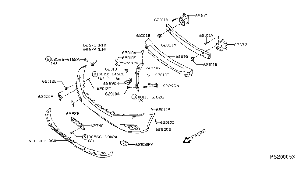
- Numbers/Labels: Each part is typically labeled with a number, which corresponds to a part number in a separate parts list.
- Exploded View: The diagram is presented in an "exploded" view, meaning that parts are slightly separated to show their relative positions and how they fit together.
How It Works: Interpreting the Diagram
Interpreting a parts diagram involves cross-referencing the visual representation with the accompanying parts list. Here's a general approach:
- Identify the System: Determine the system you're interested in (e.g., cooling system, fuel system).
- Locate the Relevant Section: Find the corresponding section in the diagram.
- Identify the Part: Locate the specific part you're looking for in the diagram.
- Note the Part Number: Record the part number associated with the identified part. This is crucial for ordering the correct replacement.
- Examine Connections: Pay attention to the lines and arrows to understand how the part connects to other components and the flow of fluids or electrical signals.
- Consult the Parts List: Use the part number to find more information about the part in the accompanying parts list, such as its description, dimensions, and material.
Real-World Use: Basic Troubleshooting Tips
Parts diagrams are incredibly useful for troubleshooting. For example, if you're experiencing a coolant leak, you can use the cooling system diagram to:
- Locate Hoses: Identify all the hoses in the cooling system and visually inspect them for cracks or leaks.
- Trace Connections: Trace the path of the coolant hoses to identify potential leak points at connections to the radiator, water pump, or engine block.
- Identify Components: Locate the water pump, thermostat housing, and other cooling system components to check for leaks or damage.
By using the diagram in conjunction with visual inspection and diagnostic tools, you can effectively pinpoint the source of the problem and take appropriate action.
Safety Considerations
Working on your vehicle can be dangerous if you're not careful. Always observe the following safety precautions:
- Disconnect the Battery: Before working on any electrical components, disconnect the negative battery terminal to prevent electrical shocks or shorts.
- Depressurize Systems: Before disconnecting any fuel lines or brake lines, depressurize the system to prevent fuel or brake fluid from spraying out.
- Wear Safety Glasses: Protect your eyes from flying debris.
- Use Jack Stands: Never work under a vehicle supported only by a jack. Use jack stands to provide secure support.
- Handle Fuel Safely: Work in a well-ventilated area when handling fuel and avoid open flames.
- Be Aware of High-Voltage Components: The ignition system (spark plugs, ignition coils) contains high-voltage components. Avoid touching these components while the engine is running.
- Cooling System: Never open the radiator cap when the engine is hot, as the coolant is under pressure and can cause severe burns.
Important: Components like the airbag system and ABS module should only be serviced by qualified technicians. Improper handling of these systems can result in serious injury.
We have the 2015 Nissan Pathfinder parts diagram available for download. Having this diagram will significantly enhance your ability to perform repairs, understand your vehicle, and undertake modifications with confidence. Remember to always prioritize safety and consult with a qualified mechanic if you are unsure about any aspect of the repair process.