
2016 F250 Upfitter Switch Wiring Diagram
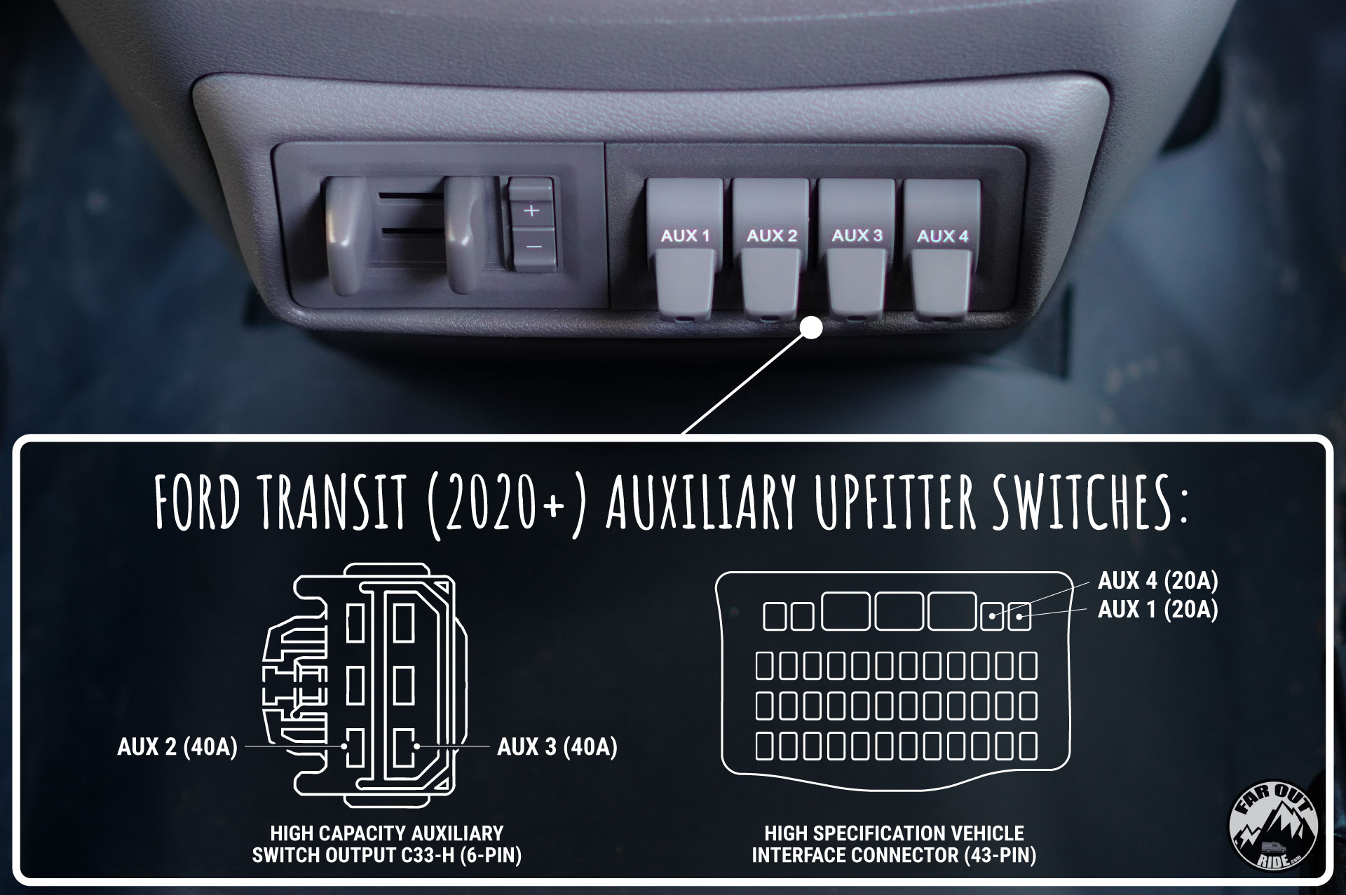
So, you're looking to tap into the upfitter switches on your 2016 Ford F-250 Super Duty? Smart move! These switches provide a convenient and professional-looking way to control aftermarket accessories like lights, winches, and air compressors without splicing into factory wiring. Understanding the wiring diagram is absolutely crucial for safely and effectively using these switches. This article will break down the 2016 F-250 upfitter switch wiring diagram, explain its components, and provide practical advice for using and troubleshooting it.
Why You Need This Diagram
The 2016 F-250 upfitter switch wiring diagram isn't just a nice-to-have; it's essential for a number of reasons:
- Safe Accessory Installation: Properly connecting accessories to the upfitter switches prevents damage to your truck's electrical system and reduces the risk of fire.
- Troubleshooting: If an accessory connected to an upfitter switch stops working, the diagram is invaluable for tracing the fault.
- Learning and Understanding: Understanding how the upfitter switches are wired into the vehicle gives you a deeper understanding of your truck's electrical system.
- Future Modifications: Knowing the wiring scheme makes it easier to plan and implement future electrical modifications.
Key Specs and Main Parts
Let's dive into the essential components and specifications of the 2016 F-250 upfitter switch system:
- Upfitter Switches: Located on the dashboard, typically above the radio, these switches control the power to the auxiliary circuits. The 2016 F-250 usually comes with 4 upfitter switches.
- Relay Box: Situated under the hood, this box houses the relays that switch the power to the upfitter circuits.
- Fuses: Located in the power distribution box (fuse box), these protect the upfitter circuits from overcurrent.
- Wiring Harness: A dedicated harness connects the upfitter switches to the relay box and provides the output wires for connecting your accessories.
- Ground Points: Secure grounding is *critical* for proper operation. These are usually located on the chassis or body of the truck.
- Power Source: The upfitter switches draw power directly from the truck's battery through a fused connection.
Important Specifications:
- Amperage Ratings: The upfitter switches have different amperage ratings. Typically, two switches are rated for higher amperage (e.g., 25-30 amps) and two are rated for lower amperage (e.g., 10-15 amps). *Always* check the specific ratings for your truck in the owner's manual or the wiring diagram. Exceeding these ratings can damage the switches and relays.
- Wire Gauge: The wire gauge (thickness) used in the upfitter harness is matched to the amperage rating of each circuit. Using the correct wire gauge is essential for safe operation.
- Voltage: The system operates at the truck's standard voltage (12V DC).
Understanding the Symbols: Deciphering the Diagram
Wiring diagrams use standardized symbols to represent electrical components and connections. Here's a breakdown of some common symbols you'll encounter in the 2016 F-250 upfitter switch wiring diagram:
- Lines: Solid lines represent wires. Thicker lines usually indicate wires with higher current-carrying capacity (larger gauge).
- Dashed Lines: Dashed lines often represent wires that are optional or only present in certain configurations.
- Circles: Circles with numbers inside usually represent wires and their corresponding identifiers, as well as ground connections.
- Squares: Squares often represent components like relays or switches.
- Rectangles: Can also represent components, especially fuses or connectors.
- Zigzag Lines: Represent resistors.
- Ground Symbol: A symbol resembling an upside-down tree or a series of decreasing lines, indicating a connection to ground.
- Colors: Wire colors are indicated by abbreviations or color codes (e.g., BLU for blue, RED for red, BLK for black). *Pay close attention to the color coding!*
Connectors: The diagram will show connectors as interlocking shapes. These show where the wiring harness connects to other parts of the vehicle's electrical system. Identifying these connectors is essential for tracing circuits and making sure your accessory connections are solid.
How It Works: Tracing the Circuit
Let's trace the flow of electricity through a typical upfitter switch circuit:
- Power Source: Power originates from the truck's battery, protected by a fuse in the main power distribution box.
- Upfitter Switch: When you flip an upfitter switch, it sends a signal to the corresponding relay in the relay box.
- Relay Activation: The signal from the switch energizes the relay's coil, which closes the relay's contacts.
- Power to Accessory: Closing the relay contacts allows power to flow from the battery, through the relay, and out to the accessory connection point (usually under the hood or near the firewall).
- Ground: The accessory completes the circuit by being connected to a suitable ground point on the vehicle's chassis.
The relay is a crucial component. It acts as an electrically controlled switch, allowing a small current from the upfitter switch to control a much larger current to the accessory. This prevents the upfitter switch itself from being overloaded.
Real-World Use: Troubleshooting and Tips
Here are some practical tips for using the wiring diagram to troubleshoot common problems:
- Accessory Not Working: First, check the fuse for that particular upfitter switch circuit. A blown fuse is the most common cause.
- Switch Not Activating Relay: Use a multimeter to check if the switch is sending a signal to the relay when it's flipped. If not, the switch may be faulty.
- Relay Not Switching: If the switch is sending a signal, but the relay isn't switching, the relay itself may be faulty. You can test the relay by applying power to its coil and checking if the contacts close.
- Voltage Drop: Use a multimeter to check the voltage at the accessory connection point. A significant voltage drop indicates a problem with the wiring, such as a loose connection or a corroded ground.
- Ground Issues: Ensure the accessory is properly grounded. A poor ground connection can cause all sorts of electrical problems. Clean and tighten ground connections regularly.
Important Tools:
- Multimeter: Essential for measuring voltage, current, and resistance.
- Test Light: A simple tool for checking if a circuit is powered.
- Wire Strippers/Crimpers: For making secure wire connections.
- Wiring Diagram: Absolutely essential!
Safety First! Handling Risky Components
Working with automotive electrical systems can be dangerous. Here are some crucial safety precautions:
- Disconnect the Battery: Always disconnect the negative terminal of the battery before working on the electrical system. This prevents accidental shorts and potential electrocution.
- Work in a Well-Ventilated Area: Batteries can release flammable gases.
- Avoid Water: Never work on electrical systems in wet conditions.
- Use Insulated Tools: Use tools with insulated handles to prevent electrical shock.
- Proper Wiring Techniques: Use proper wiring techniques, such as soldering and heat-shrinking connections, to ensure secure and reliable connections. Avoid using wire nuts in automotive applications.
- Be Mindful of Airbags: Be extremely careful when working near airbag modules. Accidental activation can cause serious injury. Refer to the service manual for proper procedures.
- Fuses Are Your Friends: Never bypass or replace fuses with higher amperage ratings. Fuses are designed to protect the electrical system from overcurrent.
The upfitter switches provide a *fantastic* way to add accessories to your 2016 F-250. Understanding the wiring diagram, respecting amperage ratings, and following safety precautions will allow you to make modifications confidently and safely.
Now that you have an understanding of the 2016 F250 Upfitter Switch Wiring Diagram, we have the file you requested, and you can download the diagram by clicking this button. Download the Diagram (Please note this is a placeholder link; a real link would direct to the actual diagram file.)