
2016 Ford F 150 Cooling System Diagram
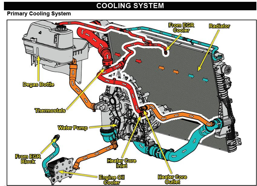
Alright, let's dive into the cooling system of the 2016 Ford F-150. Understanding this system is crucial for maintaining your truck's performance and preventing catastrophic engine damage. Whether you're tackling a repair, planning a modification, or simply want to understand your vehicle better, having a solid grasp of the cooling system is invaluable. This article will break down the system using the cooling system diagram, explaining its components, function, and how to troubleshoot common issues.
Purpose of the Cooling System Diagram
The cooling system diagram serves as a roadmap for the entire cooling system. It's not just a pretty picture; it's a crucial tool for:
- Diagnostics: Pinpointing the source of a leak, overheating issue, or other cooling-related problem.
- Repairs: Guiding you through component replacement, ensuring proper hose routing and connection.
- Modifications: Understanding the system's limitations before making performance upgrades that might increase engine heat.
- Learning: Providing a visual aid for understanding how the cooling system works as a whole.
Think of it as the blueprint for the cooling system. Without it, you're flying blind.
Key Specs and Main Parts
The 2016 F-150, depending on the engine configuration (2.7L EcoBoost, 3.5L EcoBoost, 3.5L Ti-VCT, 5.0L Ti-VCT), will have slight variations in the cooling system layout, but the fundamental components remain the same. Here are the core parts and some common specifications:
- Radiator: The primary heat exchanger. It's a network of tubes and fins that dissipates heat from the coolant into the air flowing through it. Radiator capacity can vary, but a common size is around 1.5-2 gallons. The radiator pressure cap is typically rated around 16 PSI.
- Coolant Reservoir (Expansion Tank): Holds extra coolant to compensate for expansion and contraction as the engine heats up and cools down. It also provides a point to add coolant.
- Water Pump: Circulates coolant throughout the engine and cooling system. It is typically driven by the serpentine belt.
- Thermostat: Regulates the engine temperature by controlling coolant flow to the radiator. A common thermostat opening temperature is around 195°F (90°C).
- Coolant Hoses: Connect all the components, carrying coolant throughout the system. These come in varying diameters.
- Cooling Fan: Draws air through the radiator, enhancing heat dissipation. The F-150 typically uses an electric fan or fans, controlled by the PCM (Powertrain Control Module).
- Heater Core: A small radiator located inside the vehicle's cabin, providing heat for the climate control system.
- Engine Block and Cylinder Head Coolant Passages: These are internal passages within the engine casting through which coolant flows to remove heat.
- Transmission Cooler (if equipped): Some F-150 models may have an integrated transmission cooler within the radiator or a separate cooler.
Symbols: Lines, Colors, and Icons
Understanding the symbols on the cooling system diagram is critical for proper interpretation.
- Solid Lines: Typically represent hoses or hard lines carrying coolant.
- Dashed Lines: Often indicate vacuum lines or control wires related to the cooling system (e.g., electric fan control).
- Arrows: Indicate the direction of coolant flow.
- Colors: Color coding can vary depending on the specific diagram. However, common conventions include:
- Blue or Green: Often represents cooler coolant.
- Red: Indicates hotter coolant.
- Icons: Symbols are used to represent components. For instance:
- A rectangle with fins usually represents the radiator.
- A circle with a propeller-like shape represents the water pump.
- A symbol resembling a valve usually represents the thermostat.
The legend accompanying the diagram will provide a comprehensive explanation of all symbols used.
How It Works
The cooling system operates on a closed-loop principle. Here's a simplified breakdown:
- The water pump circulates coolant through the engine block and cylinder heads, absorbing heat generated by combustion.
- The heated coolant flows towards the thermostat.
- If the engine is cold, the thermostat remains closed, preventing coolant from flowing to the radiator. This allows the engine to reach its optimal operating temperature quickly. Coolant is re-circulated within the engine.
- Once the engine reaches its operating temperature (determined by the thermostat's rating), the thermostat opens.
- Hot coolant now flows from the engine to the radiator.
- As coolant flows through the radiator, heat is dissipated into the air, aided by the cooling fan(s).
- The cooled coolant returns to the water pump, completing the cycle.
- The coolant reservoir acts as an overflow and maintains system pressure.
- If the vehicle's heater is turned on, coolant also flows through the heater core, providing heat to the cabin.
It's a continuous cycle of heat absorption and dissipation, crucial for preventing engine overheating.
Real-World Use: Basic Troubleshooting Tips
The cooling system diagram can significantly aid in troubleshooting. Here are some basic tips:
- Overheating: Check coolant level, inspect the radiator for blockages (leaves, bugs), verify the thermostat is opening, and ensure the cooling fan is functioning correctly. Use the diagram to trace coolant flow and identify potential restrictions. A non-functioning water pump will also cause overheating.
- Coolant Leaks: Visually inspect all hoses, connections, the radiator, and the water pump for signs of leaks. The diagram helps you locate these components quickly. Look for dried coolant residue, which often appears as a crusty, colored deposit. Don't forget to check the weep hole on the water pump for signs of leakage, indicating seal failure.
- No Heat in Cabin: Check coolant level, verify the heater core hoses are hot, and inspect the blend door actuator (controls airflow over the heater core). The diagram will show the heater core's location and hose connections.
- Low Coolant Warning: Identify the sensor using the diagram and check its wiring and connection. Also, inspect for leaks, as mentioned above. A faulty sensor can also cause a false reading.
Important: Always allow the engine to cool completely before opening the radiator cap. The system is pressurized, and hot coolant can cause severe burns.
Safety: Risky Components
The cooling system operates under pressure and at high temperatures. Exercise caution when working on it:
- Hot Coolant: As mentioned, avoid contact with hot coolant. Allow the engine to cool completely before opening the radiator cap or disconnecting any hoses.
- Pressure: The cooling system is pressurized. Relieve pressure slowly by carefully opening the radiator cap in stages. Wrap a thick towel around the cap for protection.
- Electrical Components: The cooling fan(s) and coolant temperature sensor are electrical components. Disconnect the battery before working on these to avoid electrical shock.
- Sharp Objects: The radiator fins can be sharp. Wear gloves to protect your hands.
- Used Coolant: Coolant is toxic. Dispose of used coolant properly at a recycling center or auto parts store. Never pour it down the drain.
Ignoring these safety precautions can lead to serious injury.
By understanding the cooling system diagram and its components, you can confidently diagnose and repair cooling system issues on your 2016 Ford F-150. Remember to prioritize safety and consult the service manual for specific procedures and torque specifications. We have the full cooling system diagram file available for download. It will be a valuable resource for your DIY projects.