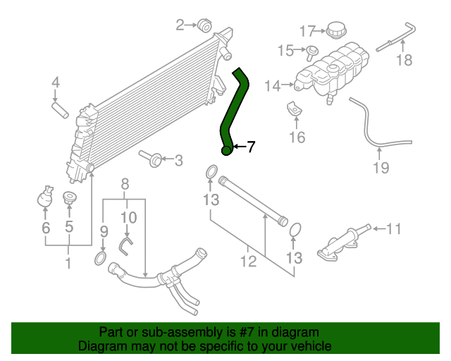
2016 Ford F150 5.0 Cooling System Diagram
Let's dive into the cooling system of a 2016 Ford F-150 with the 5.0L V8 engine. A solid understanding of this system is crucial for everything from routine maintenance to diagnosing and fixing overheating issues, planning performance modifications, or even just increasing your overall automotive knowledge. We’re going to break down the cooling system diagram, explaining its components, operation, and how to use it for practical troubleshooting.
Why This Diagram Matters
Think of the cooling system diagram as the roadmap to your engine's thermal management. It's not just a pretty picture; it's a vital tool for:
- Diagnostics: Identifying faulty components causing overheating, leaks, or other cooling-related problems.
- Repairs: Guiding you through component replacement and proper system reassembly.
- Maintenance: Planning preventative maintenance tasks like coolant flushes and hose inspections.
- Modifications: Understanding the system's capacity and limitations if you're considering performance upgrades that generate more heat (e.g., adding a supercharger).
- Learning: Gaining a deeper understanding of how your engine works and its critical support systems.
Key Specs and Main Parts of the 2016 F-150 5.0L Cooling System
The 2016 F-150 5.0L cooling system is a closed-loop, liquid-cooled system designed to maintain optimal engine operating temperature. Here's a breakdown of the key components:
- Engine Block and Cylinder Heads: Internal coolant passages circulate coolant around the cylinders and combustion chambers to absorb heat generated during combustion.
- Radiator: A heat exchanger consisting of a core with thin fins designed to dissipate heat from the coolant as air passes through it. Made of aluminum and plastic in most cases.
- Water Pump: A centrifugal pump driven by the engine's accessory belt. It circulates coolant throughout the system. The water pump's effectiveness is key to maintaining coolant flow.
- Thermostat: A temperature-sensitive valve that regulates coolant flow to the radiator. It remains closed when the engine is cold, allowing it to warm up quickly. Once the engine reaches its operating temperature (typically around 190-210°F), the thermostat opens, allowing coolant to flow to the radiator for cooling.
- Coolant Reservoir (Expansion Tank): A plastic tank that provides a space for coolant to expand as it heats up. It also allows for easy coolant level checks and topping off.
- Radiator Cap: Pressurizes the cooling system, raising the boiling point of the coolant and preventing cavitation (the formation of vapor bubbles) within the system.
- Coolant Hoses: Rubber hoses that connect the various components of the cooling system, allowing coolant to flow freely. Pay attention to hose condition.
- Cooling Fan(s): A mechanical or electric fan that draws air through the radiator, increasing its cooling capacity. The 2016 F-150 5.0L typically uses an electric fan, controlled by the engine control module (ECM).
- Heater Core: A small radiator located inside the vehicle's cabin. Hot coolant flows through the heater core, and the blower motor blows air across it, providing heat for the cabin.
- Coolant Temperature Sensor (CTS): Provides the ECM with information about the coolant temperature, which is used to control various engine functions, including fan operation and fuel mixture.
Typical Coolant Specification: Ford specifies Motorcraft Orange coolant (usually a 50/50 mix with distilled water) for this engine. Using the correct coolant is crucial to prevent corrosion and maintain optimal cooling performance. The system capacity is approximately 15 quarts.
Understanding the Diagram Symbols
The cooling system diagram uses standardized symbols to represent different components and connections. Here's a quick guide:
- Solid Lines: Represent coolant hoses or pipes. Their thickness might indicate the diameter of the hose.
- Dotted Lines: May represent vacuum lines, electrical connections, or control signals related to the cooling system.
- Arrows: Indicate the direction of coolant flow.
- Rectangles: Typically represent components like the radiator, coolant reservoir, or heater core.
- Circles: May represent sensors, valves, or other small components.
- Color Coding: Diagrams may use color to differentiate between supply and return lines, or to highlight specific circuits within the system.
Always refer to the diagram's legend for a specific explanation of the symbols used. The legend is crucial for accurate interpretation.
How the Cooling System Works
The cooling system's operation is relatively straightforward:
- The water pump circulates coolant from the engine block and cylinder heads, where it absorbs heat.
- The hot coolant flows through the thermostat. If the engine is cold, the thermostat remains closed, bypassing the radiator and allowing the coolant to recirculate through the engine.
- Once the engine reaches operating temperature, the thermostat opens, allowing hot coolant to flow to the radiator.
- In the radiator, heat is dissipated from the coolant to the air passing through the radiator core. The cooling fan(s) assist in this process.
- The cooled coolant then returns to the water pump and is circulated back through the engine.
- The coolant reservoir acts as an overflow tank, allowing coolant to expand and contract as the engine heats up and cools down.
Real-World Use: Basic Troubleshooting Tips
Here are some common cooling system problems and how the diagram can help you troubleshoot them:
- Overheating: Check coolant level, thermostat operation (is it opening?), radiator condition (is it blocked?), water pump function (is it circulating coolant?), and fan operation. The diagram helps you locate these components and trace the coolant flow.
- Coolant Leaks: Inspect all hoses, connections, and components for leaks. Use the diagram to identify the specific hose or component that's leaking. Look for telltale signs of coolant residue.
- No Heat in Cabin: Check coolant level, thermostat operation, and heater core hoses for blockage. The diagram shows the heater core's location and hose connections.
- Coolant Loss: Check the radiator cap, coolant reservoir, and all hoses for leaks. Consider a pressure test of the cooling system to identify hidden leaks.
When troubleshooting, always start with the simplest and most obvious causes first. The cooling system diagram provides a visual representation of the system, making it easier to trace potential problems.
Safety Considerations
Working on the cooling system can be dangerous. Here are some important safety precautions:
- Never remove the radiator cap when the engine is hot. The system is under pressure, and hot coolant can spray out, causing severe burns. Allow the engine to cool completely before opening the system.
- Wear safety glasses and gloves when working with coolant. Coolant can irritate your skin and eyes.
- Dispose of used coolant properly. It is toxic to humans and animals. Most auto parts stores will accept used coolant for recycling.
- Be careful when working around the cooling fan(s). They can turn on unexpectedly, even when the engine is off. Disconnect the battery or fan motor connector before working near the fan blades.
- The water pump is driven by the accessory belt. Be sure to disconnect the battery before working on the belt to prevent accidental starting of the engine.
Remember that dealing with pressurized systems always carries an element of risk. Exercise caution and double-check your work.
By understanding the cooling system diagram and its components, you can effectively diagnose and repair cooling-related problems on your 2016 Ford F-150 5.0L. This knowledge will empower you to tackle maintenance tasks with confidence and potentially save money on costly repairs.
We have a high-resolution version of the 2016 Ford F-150 5.0L cooling system diagram available for download. This detailed diagram will provide an even clearer understanding of the system's layout and components. Please reach out to us with your email, and we'll promptly send you the file.