
2016 Ford F150 Exhaust System Diagram
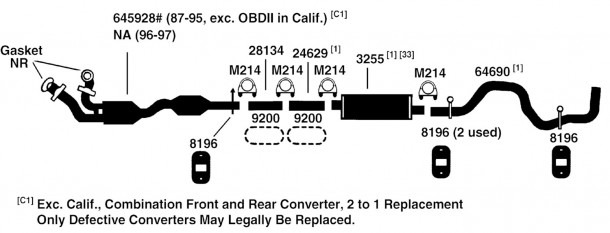
Understanding the exhaust system of your 2016 Ford F150 is crucial for performing maintenance, troubleshooting issues, and even considering performance modifications. This article will provide a detailed breakdown of the exhaust system diagram, explaining its components, function, and how to interpret it effectively. Having this knowledge empowers you to diagnose problems, make informed decisions about repairs, and potentially save money on labor costs.
Why You Need the Exhaust System Diagram
The exhaust system diagram isn't just a pretty picture; it's a blueprint for the entire system. Here's why it's so valuable:
- Troubleshooting: When you're experiencing exhaust-related problems – like excessive noise, poor fuel economy, or failing emissions tests – the diagram helps pinpoint the source of the issue.
- Repair and Replacement: Identifying the correct part number and location is essential when replacing components. The diagram provides a visual reference.
- Performance Upgrades: If you're considering upgrading your exhaust system for better performance or sound, understanding the stock configuration is a must. Knowing where sensors are located and how the system flows is crucial.
- Learning: Even if you're not currently experiencing issues, studying the diagram can improve your overall understanding of automotive systems.
2016 Ford F150 Exhaust System: Key Specs and Main Parts
The 2016 Ford F150 exhaust system varies slightly depending on the engine (2.7L EcoBoost, 3.5L EcoBoost, 3.5L Ti-VCT, or 5.0L Coyote V8) and cab configuration. However, the core components remain consistent. We'll focus on the general principles applicable to most models.
Major Components:
- Exhaust Manifolds: These are bolted directly to the engine's cylinder heads and collect exhaust gases from each cylinder. They are often made of cast iron or, in performance applications, stainless steel. The design is critical to efficient exhaust flow.
- Catalytic Converters: A critical emissions control device. Catalytic converters use chemical reactions to convert harmful pollutants (hydrocarbons, carbon monoxide, and nitrogen oxides) into less harmful substances (carbon dioxide, water, and nitrogen). The 2016 F150 typically has two or more catalytic converters.
- Oxygen (O2) Sensors: These sensors monitor the oxygen content in the exhaust stream, both before (upstream) and after (downstream) the catalytic converters. This data is fed back to the engine control unit (ECU) to optimize fuel injection and ensure efficient catalytic converter operation.
- Muffler: The muffler reduces exhaust noise by using internal chambers and baffles to dampen sound waves.
- Resonators (Optional): Some F150 models include resonators, which further reduce noise and control exhaust tone.
- Tailpipe: The final section of the exhaust system, which directs exhaust gases away from the vehicle.
- Pipes and Connectors: These connect the various components of the exhaust system. Flanges, clamps, and hangers are used to secure the pipes and ensure a leak-free seal.
Material Considerations:
The exhaust system is typically constructed from aluminized steel or stainless steel. Aluminized steel offers a balance of cost and corrosion resistance, while stainless steel provides superior durability and resistance to rust. Performance exhaust systems often use higher-grade stainless steel for improved longevity.
Decoding the Exhaust System Diagram: Symbols and Conventions
Understanding the symbols and conventions used in the diagram is essential for proper interpretation.
- Lines:
- Solid Lines: Generally represent exhaust pipes or tubing. The thickness of the line may indicate the diameter of the pipe.
- Dashed Lines: May represent vacuum lines associated with the exhaust system (for example, on older models with exhaust gas recirculation - EGR). However, on a 2016 F150, dashed lines are less common.
- Colors: Color coding can vary depending on the specific diagram manufacturer. However, common conventions include:
- Black: General exhaust piping.
- Red: Hot exhaust gases. (Sometimes used to highlight sections prone to high temperatures).
- Green/Blue: May indicate the location of sensors or other electronic components.
- Icons:
- Rectangles: Often represent catalytic converters, mufflers, or resonators. The diagram may include internal details of these components.
- Circles: Typically used to denote sensors (O2 sensors) or connection points.
- Triangles: Can represent mounting points or hangers.
Always refer to the diagram's legend or key to confirm the meaning of specific symbols and colors. The legend will provide the definitive explanation for the diagram's conventions.
How It Works: The Exhaust Flow
The exhaust system's primary function is to remove combustion byproducts from the engine while minimizing noise and emissions. Here's a step-by-step overview of the process:
- Exhaust Gases Exit Cylinders: After combustion, exhaust gases are expelled from the engine cylinders into the exhaust manifolds.
- Collection and Flow: The manifolds collect the gases from multiple cylinders and direct them into a single (or sometimes two) downpipe.
- Catalytic Conversion: The exhaust gases then flow through the catalytic converters. These convert harmful pollutants into less harmful substances using a catalyst (usually platinum, palladium, and rhodium).
- Oxygen Sensor Feedback: O2 sensors monitor the exhaust gas composition before and after the catalytic converters, providing feedback to the ECU to optimize engine performance and emissions control.
- Noise Reduction: The muffler uses internal chambers and baffles to dampen sound waves, reducing exhaust noise. Resonators, if present, further refine the exhaust tone.
- Discharge: Finally, the exhaust gases are discharged into the atmosphere through the tailpipe.
Real-World Use: Basic Troubleshooting
Using the exhaust system diagram, you can perform some basic troubleshooting. Here are a few examples:
- Excessive Noise: Check the diagram to locate the muffler and resonators. Inspect these components for rust, holes, or damage. Also, check the pipe connections (flanges, clamps) for leaks.
- Check Engine Light (CEL) Related to O2 Sensors: The diagram shows the location of the O2 sensors. Use a scan tool to read the diagnostic trouble codes (DTCs). The diagram will help you identify which sensor is reporting a problem. For example, a P0131 code indicates a low voltage reading from the upstream O2 sensor on bank 1.
- Exhaust Leaks: Visually inspect the exhaust system, following the diagram, for signs of leaks, such as rust, soot buildup, or damage. Pay close attention to joints and connections. A common symptom is a hissing or ticking sound, especially when the engine is cold.
Important: Always use proper safety precautions when working on the exhaust system. Exhaust components can be extremely hot.
Safety Considerations: Hot Components
The exhaust system reaches extremely high temperatures during operation. Burns are a significant risk.
- Allow the exhaust system to cool completely before working on it. This can take several hours.
- Wear appropriate personal protective equipment (PPE), including gloves and eye protection.
- Work in a well-ventilated area. Exhaust fumes contain harmful gases.
- When loosening rusted bolts or fasteners, use penetrating oil and appropriate tools to avoid damaging the components.
- Be extremely careful when working near the catalytic converter, as it contains precious metals and tampering with it is illegal.
Working on your exhaust system can be rewarding. The exhaust system diagram will guide you when doing repair and replacement. We have the diagram available for download, enabling you to get started with your work as soon as possible.