2016 Nissan Altima Fuse Box Diagram
So, you're wrestling with a 2016 Nissan Altima and suspect a blown fuse? Or maybe you're planning some electrical modifications? Either way, understanding your car's fuse box is crucial. This article will break down the 2016 Altima's fuse box diagram, offering the knowledge you need for repairs, modifications, and a deeper understanding of your vehicle's electrical system.
Why Understanding the Fuse Box Matters
Think of the fuse box as the central nervous system's junction box for your car's electrical circuits. It's designed to protect these circuits from overcurrent – excessive electrical flow that can damage components or even start a fire. When a circuit draws too much current (due to a short circuit or a faulty component), the fuse blows, interrupting the flow of electricity and preventing further damage.
A solid understanding of the fuse box and its diagram is essential for:
- Troubleshooting Electrical Issues: Identifying a blown fuse is often the first step in diagnosing electrical problems like non-functioning lights, accessories, or even starting issues.
- Performing Repairs: Replacing a blown fuse is a simple repair, but you need to know which fuse controls which circuit.
- Making Electrical Modifications: Adding aftermarket accessories like lighting, stereos, or alarms requires tapping into the existing electrical system. Knowing the fuse assignments helps you avoid overloading circuits and ensures proper operation.
- Preventing Damage: Incorrectly replacing a blown fuse with one of a higher amperage can bypass the circuit's protection and cause serious damage to the wiring and components.
Key Specs and Main Parts of the 2016 Altima Fuse Box
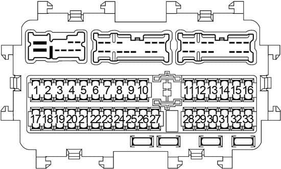
The 2016 Nissan Altima typically has two main fuse box locations:
- Interior Fuse Box: Located inside the cabin, usually under the dashboard on the driver's side. It's often behind a small access panel. This box primarily houses fuses for interior components like lights, radio, power windows, and the climate control system.
- Engine Compartment Fuse Box: Located in the engine bay, near the battery. This box contains fuses for critical engine management systems, exterior lighting, and other high-current components like the starter motor and the ABS system.
Key Specs: The fuses themselves come in various amperages (measured in amps, or A). Common values include 5A, 7.5A, 10A, 15A, 20A, 25A, 30A, and higher for some engine compartment fuses. Each fuse is designed to break the circuit at its rated amperage to prevent damage. The fuse box lid usually has a diagram indicating each fuse's function and amperage rating.
Fuse Types: The 2016 Altima primarily uses blade-type fuses, specifically ATO/ATC (Automotive Technology Organization/Automotive Technology Council) and mini-blade fuses. These fuses are color-coded to indicate their amperage rating. You'll also find relays within the fuse box. Relays are electromechanical switches that allow a low-current circuit to control a high-current circuit (e.g., using a small switch on your dashboard to control the high-current headlight circuit).
Decoding Fuse Box Symbols
Understanding the symbols used on the fuse box diagram is crucial for proper identification.
- Lines: Lines represent electrical circuits connecting various components. A thicker line might indicate a higher-current circuit.
- Colors: Fuse colors are standardized to indicate amperage. For example:
- Yellow: 20A
- Blue: 15A
- Red: 10A
- Brown: 7.5A
- Orange: 5A
- Icons: These are the most important part of the diagram. Common icons include:
- Light Bulb: Indicates a lighting circuit (headlights, tail lights, interior lights).
- Radio Antenna: Represents the radio or infotainment system.
- Fan: Usually indicates the climate control system (blower motor, AC compressor).
- Steering Wheel: Could represent power steering.
- Engine Block: Indicates an engine management system component (fuel pump, ignition system).
- Horn: The horn circuit.
- Window: Power windows.
- Lock: Power door locks.
The specific symbols used can vary slightly, but the general principle remains the same: each symbol represents a specific component or system that the fuse protects. Always refer to the legend printed on the fuse box cover or in your owner's manual for the exact meaning of each symbol.
How It Works: Fuse Protection in Action
Let's imagine the circuit for your Altima's radio is protected by a 10A fuse. The radio is designed to draw a certain amount of current under normal operating conditions – say, 8 amps. As long as the current draw remains below 10A, the fuse remains intact, and the radio functions properly.
Now, let's say there's a short circuit in the radio wiring. This short circuit causes the radio to draw significantly more current – perhaps 15 amps. This excessive current heats up the fuse element (a thin wire or metal strip inside the fuse). The fuse element is designed to melt and break the circuit when it exceeds its rated amperage (10A in this case). This interruption of the circuit prevents the short circuit from damaging the radio, the wiring, or potentially causing a fire.
Real-World Use: Basic Troubleshooting
If you notice a component isn't working, follow these steps:
- Consult the Owner's Manual/Diagram: Locate the fuse box diagram in your owner's manual or on the fuse box cover. Identify the fuse associated with the non-functioning component.
- Visually Inspect the Fuse: Remove the fuse using a fuse puller (usually located in one of the fuse boxes or in the engine compartment). Hold the fuse up to the light and look for a broken filament. If the filament is broken, the fuse is blown.
- Test the Fuse (Optional): For a more accurate test, use a multimeter in continuity mode. If the multimeter shows continuity (a beep or a reading of 0 ohms), the fuse is good. If there's no continuity, the fuse is blown.
- Replace the Fuse: Replace the blown fuse with a new fuse of the same amperage. Never use a fuse with a higher amperage rating.
- Test the Component: Turn on the component to see if it now works.
- If the Fuse Blows Again: If the new fuse immediately blows again, this indicates a persistent short circuit or overload in the circuit. Further diagnostics are needed, and you may want to consult a professional mechanic.
Safety First! Risky Components
Working with electrical systems involves inherent risks. Be particularly cautious when dealing with the following:
- Airbag System Fuses: Fuses associated with the Supplemental Restraint System (SRS), including airbags, should be handled with extreme care. Disconnecting and reconnecting these fuses can potentially trigger the airbags. Consult a qualified technician before working on any airbag-related circuits.
- Engine Control Module (ECM) Fuses: These fuses protect the ECM, which controls crucial engine functions. Incorrectly handling these fuses can lead to engine damage or performance issues.
- High-Amperage Fuses: Fuses with high amperage ratings (e.g., those for the starter motor or alternator) carry a significant electrical load. Short-circuiting these circuits can result in sparks, burns, or even electrical shock.
- Battery: Always disconnect the negative battery terminal before working on the electrical system to prevent accidental short circuits and electrical shocks.
Important: Always disconnect the negative battery terminal before working on any electrical component to prevent accidental shorts and potential injuries. Using the incorrect amperage fuse can lead to serious damage or fire. Always consult the owner's manual and the fuse box diagram.
By understanding the 2016 Nissan Altima's fuse box diagram, you can confidently troubleshoot electrical issues, perform minor repairs, and even tackle some electrical modifications. Remember safety is paramount – when in doubt, consult a qualified mechanic.
We have the complete 2016 Nissan Altima Fuse Box Diagram file available for download. It includes detailed illustrations and specifications for both the interior and engine compartment fuse boxes.