
2016 Nissan Frontier Fuse Box Diagram
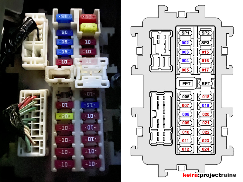
The 2016 Nissan Frontier is a reliable truck, but like any vehicle, electrical issues can arise. Understanding the fuse box diagram is crucial for diagnosing and resolving these problems. This article provides a detailed guide to the 2016 Nissan Frontier fuse box, enabling you to confidently tackle electrical repairs, modifications, or simply gain a deeper understanding of your vehicle's electrical system.
Purpose of the Fuse Box Diagram
The fuse box diagram is essentially a roadmap of your truck's electrical system. It identifies the function and amperage rating of each fuse and relay. This information is invaluable for:
- Troubleshooting Electrical Problems: When an electrical component malfunctions (e.g., a headlight stops working), the first step is often checking the corresponding fuse. The diagram helps you locate the correct fuse quickly.
- Performing Modifications: If you're adding aftermarket accessories (e.g., auxiliary lights, a trailer brake controller), you'll need to tap into the existing electrical system. The diagram helps you identify appropriate power sources and ensure proper fusing to prevent overloads.
- Preventing Further Damage: Replacing a blown fuse with one of a higher amperage rating can overload the circuit and cause significant damage, potentially leading to a fire. The diagram ensures you use the correct replacement fuse.
- General Understanding: Even if you don't plan on performing electrical work yourself, understanding the fuse box layout provides a better grasp of how your vehicle's systems operate.
Key Specs and Main Parts
The 2016 Nissan Frontier typically has two main fuse box locations:
- Interior Fuse Box: Located inside the cabin, usually under the dashboard on the driver's side. This box primarily houses fuses for interior components like lights, the radio, power windows, and the climate control system.
- Engine Compartment Fuse Box: Located in the engine bay, often near the battery. This box contains fuses and relays for engine management systems, headlights, the horn, and other critical vehicle functions.
Key Components:
- Fuses: Sacrificial devices designed to protect electrical circuits from overcurrent. They contain a thin wire that melts and breaks the circuit if the current exceeds a specified amperage.
- Relays: Electrically operated switches that allow a low-current circuit to control a high-current circuit. Relays are used to switch on components like headlights, the starter motor, and the fuel pump.
- Fuse Puller: A small plastic tool used to safely remove and install fuses.
- Test Light or Multimeter: Used to test fuses for continuity (whether current can flow through them). A multimeter offers more advanced testing capabilities.
Symbols, Lines, Colors, and Icons
Fuse box diagrams employ various symbols, colors, and icons to represent different components and functions. Understanding these symbols is essential for accurate interpretation.
- Fuse Symbols: Fuses are typically represented by a rectangular or square symbol with a zigzag line inside. The diagram usually indicates the amperage rating of the fuse (e.g., 10A, 15A, 20A).
- Relay Symbols: Relays are often represented by a square or rectangular symbol with internal coils and switch contacts. The diagram may indicate the relay's function (e.g., "Headlight Relay," "Fuel Pump Relay").
- Lines: Solid lines represent electrical wires connecting components. Dashed lines may indicate ground connections or circuits that are only active under certain conditions.
- Colors: Wire colors are sometimes indicated on the diagram (e.g., BLU for blue, RED for red, GRN for green). This helps in tracing wires within the harness.
- Icons: Specific components, such as the windshield wiper motor or the horn, may be represented by simplified icons. Look for a legend or key on the diagram that explains the meaning of each icon.
Amperage Rating: This is a crucial detail. Always replace a blown fuse with one of the same amperage rating. Using a higher amperage fuse can bypass the circuit's protection and lead to overheating or fire.
How It Works
The electrical system of your 2016 Nissan Frontier is a complex network of circuits, each protected by a fuse. When an electrical component is activated (e.g., you turn on the headlights), current flows through the circuit to power that component. If there's a short circuit or excessive current draw, the fuse's internal wire heats up and melts, breaking the circuit and preventing damage to other components. The fuse box is the central distribution point for all these circuits, containing the fuses and relays that control and protect them.
Relays allow low-current circuits to control high-current circuits. For example, the headlight switch itself carries a low current, but it activates a relay that switches on the high-current headlight circuit. This protects the switch from damage and allows it to be smaller and more easily accessible.
Real-World Use – Basic Troubleshooting Tips
Here's how to use the fuse box diagram for basic troubleshooting:
- Identify the Problem: Determine which electrical component is malfunctioning (e.g., the power windows aren't working).
- Consult the Diagram: Locate the interior fuse box diagram (usually in the owner's manual or a label inside the fuse box cover). Find the fuse that corresponds to the malfunctioning component.
- Inspect the Fuse: Visually inspect the fuse. If the wire inside is broken or blackened, the fuse is blown.
- Test the Fuse (Optional): Use a test light or multimeter to confirm the fuse is blown. A test light will not illuminate if the fuse is blown. A multimeter set to continuity mode will not show continuity (an audible beep or a reading of 0 ohms) if the fuse is blown.
- Replace the Fuse: Replace the blown fuse with a new fuse of the same amperage rating.
- Test the Component: Turn on the component to see if it now works.
- If the Fuse Blows Again: If the new fuse blows immediately or shortly after being replaced, there's likely a short circuit or other underlying problem in the circuit. Further diagnosis is required, potentially involving a mechanic.
Safety – Highlight Risky Components
Working with automotive electrical systems can be dangerous if precautions are not taken:
- Disconnect the Battery: Before working on any electrical components, disconnect the negative (black) battery cable. This will prevent accidental short circuits and electric shocks.
- Avoid Tampering with Airbag Circuits: The airbag system is highly sensitive and potentially dangerous. Do not attempt to repair or modify airbag-related circuits unless you are specifically trained and qualified to do so. Airbags can deploy unexpectedly and cause serious injury.
- Use the Correct Fuses: Always use fuses with the correct amperage rating. Using a higher amperage fuse can overload the circuit and cause a fire.
- Wear Safety Glasses: Protect your eyes from sparks or debris.
- Work in a Well-Ventilated Area: Some electrical components may emit fumes.
High-Risk Components: Pay special attention when working around the following:
- Airbag Control Module: As mentioned above, this is a highly sensitive and potentially dangerous system.
- Fuel Pump Relay and Wiring: Fuel is flammable, so exercise caution when working with the fuel pump circuit.
- Ignition System: The ignition system operates at high voltages and can deliver a shock.
Remember, if you're unsure about any aspect of electrical repair, it's always best to consult a qualified mechanic.
We have a detailed 2016 Nissan Frontier Fuse Box Diagram file available for download, that includes both interior and engine compartment fuse locations. This will provide a visual reference and can significantly aid in your troubleshooting and repair efforts. To access the file, please look for the download link provided below.
Disclaimer: This information is intended for educational purposes only and should not be considered a substitute for professional advice. Always consult a qualified mechanic for any complex or potentially dangerous repairs. We are not responsible for any damages or injuries resulting from the use of this information.