2016 Nissan Pathfinder Alternator Wiring Diagram
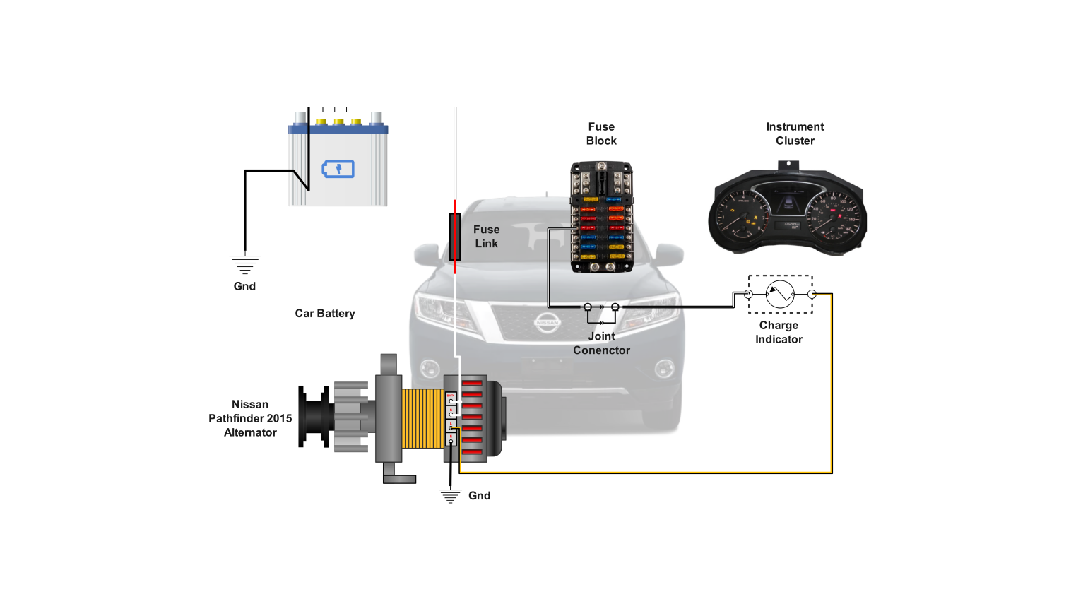
Alright, let's dive into the alternator wiring diagram for the 2016 Nissan Pathfinder. Understanding this diagram is crucial for anyone tackling electrical repairs, performing upgrades (like adding high-powered audio systems), or simply expanding your automotive knowledge. This isn't just about blindly following wires; it's about understanding the system so you can diagnose problems effectively and make informed decisions.
Purpose of the Alternator Wiring Diagram
The wiring diagram is your roadmap to the Pathfinder's charging system. It provides a visual representation of how the alternator, battery, starter, and other related components are interconnected. With this, you can:
- Troubleshoot charging issues like a dead battery, dimming headlights, or a charging system warning light.
- Identify and repair faulty wiring, connectors, or components.
- Install aftermarket accessories that require a connection to the charging system.
- Understand the overall electrical architecture of your vehicle.
Key Specs and Main Parts
Before we delve into the diagram, let's identify the major players in the 2016 Pathfinder's charging system. Keep in mind that minor variations *may* exist based on specific trim levels, but the core principles remain the same.
- Alternator: The heart of the charging system. It converts mechanical energy from the engine into electrical energy to charge the battery and power the vehicle's electrical loads. The 2016 Pathfinder typically uses an alternator rated between 130 and 150 amps, depending on the options package. Knowing the amperage is vital when diagnosing issues and ensuring correct replacement part selection.
- Battery: Stores electrical energy and provides power to start the engine and operate electrical components when the engine isn't running. It's typically a 12-volt battery.
- Starter Motor: Crank's the engine to initiate combustion. Requires a significant amount of current from the battery.
- Ignition Switch: Controls the flow of power to various circuits, including the alternator field (excitation) circuit.
- Voltage Regulator: Typically integrated inside the alternator, this component maintains a constant output voltage (around 13.5-14.5 volts) to prevent overcharging the battery and damaging electrical components.
- Battery Management System (BMS): Newer vehicles, including some 2016 Pathfinders, may incorporate a BMS. This system monitors battery condition and adjusts charging parameters for optimal performance and longevity. It communicates with the Engine Control Module (ECM).
- Fuses and Fusible Links: Protective devices that prevent damage from overcurrent conditions. These are critical for safety and must be inspected during troubleshooting.
Symbols in the Diagram
Understanding the symbols in the wiring diagram is paramount. Here's a breakdown of what you'll typically find:
- Solid Lines: Represent wires. The thickness of the line *doesn't* typically indicate wire gauge, but it distinguishes between wires and other elements.
- Dashed Lines: May represent shielding, ground connections, or communication buses (like CAN bus lines).
- Colors: Each wire is designated by a color code (e.g., "B" for black, "R" for red, "W" for white, "G" for green, "L" for blue, "Y" for yellow). Multiple colors may be used for a single wire if it changes color at a connector. For example, "R/B" would indicate a red wire with a black stripe.
- Circles and Squares: Represent connectors and terminals. Connectors are often numbered or lettered to aid in identification.
- Rectangles: Typically represent components like relays, switches, or control modules (like the ECM or BMS).
- Ground Symbol ( ): Indicates a connection to the vehicle's chassis ground (negative terminal of the battery). Extremely important – improper grounding can cause all sorts of electrical problems.
- Fuse Symbol: A wavy line inside a rectangle indicates a fuse.
- Alternator Symbol: Usually a circle with an "ALT" or stylized representation of an alternator inside.
- Battery Symbol: A series of short, alternating positive and negative lines.
How It Works: Simplified Explanation
Here's a simplified overview of how the 2016 Pathfinder's charging system works:
- When the engine starts, the crankshaft turns the alternator's pulley via a belt.
- The rotating alternator generates AC (Alternating Current) electricity.
- This AC electricity is converted to DC (Direct Current) by diodes within the alternator (a process called rectification).
- The voltage regulator monitors the battery voltage and controls the amount of current supplied by the alternator to maintain a stable charging voltage (around 13.5-14.5V).
- The alternator's output is fed to the battery, replenishing the energy used during starting and powering the vehicle's electrical loads (lights, radio, A/C, etc.).
- The excitation circuit, often powered through the ignition switch, provides the initial voltage required to start the alternator's charging process. This is often indicated by the charging warning light on the dashboard; if this light is on while driving, it usually signals a problem with the charging system.
Real-World Use: Basic Troubleshooting Tips
Let's put this knowledge to practical use with some basic troubleshooting.
- Dead Battery: Check the battery voltage with a multimeter. If it's significantly low (below 12V), either the battery is faulty or it's not being charged properly. Use the wiring diagram to trace the charging circuit and check for loose connections, corroded terminals, or blown fuses. Also, test the alternator's output voltage with the engine running. It should be within the 13.5-14.5V range. A reading outside this range indicates a faulty alternator or voltage regulator.
- Charging System Warning Light: This light indicates a potential problem with the charging system. Start by checking the alternator belt for proper tension and condition. Then, use the wiring diagram to check the connections to the alternator and voltage regulator. Use a scan tool to check for diagnostic trouble codes (DTCs) related to the charging system.
- Dimming Headlights: Could indicate a low charging voltage. Perform the same voltage tests as described above.
- High Battery Voltage Overcharging the battery can indicate a faulty voltage regulator, or, in some cases, a faulty battery temperature sensor causing the BMS to mismanage the charging.
- Don't just replace the alternator! Use the wiring diagram to verify proper grounding, check all related fuses, and test the excitation circuit before assuming the alternator itself is the problem. Often, a simple wiring issue or blown fuse is the culprit.
Safety Considerations
Working with automotive electrical systems can be dangerous. Here are some crucial safety precautions:
- Disconnect the negative battery terminal before working on any electrical components. This prevents accidental short circuits and potential electrocution.
- Be careful when working around the alternator. Even with the battery disconnected, the alternator can retain a residual charge.
- Never pierce wires to test them unless absolutely necessary. This can damage the insulation and create a potential short circuit. Use back probing techniques or connector test kits instead.
- Use a multimeter to check for voltage and continuity. Never rely on visual inspection alone.
- If you're not comfortable working with electrical systems, consult a qualified mechanic.
- Fuses and Fusible Links are your friends! They protect the system, and should be replaced with same amperage rating. Never bypass or use a higher amperage rating as this could cause serious damage or fire.
We have the 2016 Nissan Pathfinder Alternator Wiring Diagram file available. Contact us if you need a copy to download. It's a valuable resource for anyone working on this vehicle's electrical system.