
2016 Nissan Sentra Radio Wiring Diagram
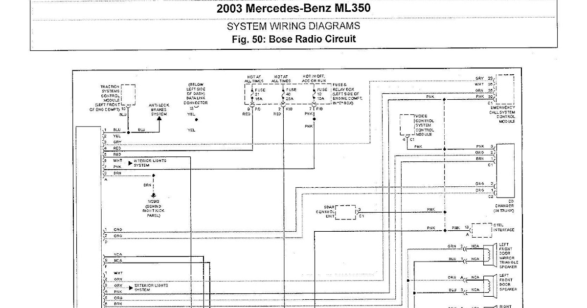
So, you're diving into the audio system of your 2016 Nissan Sentra? Excellent! This article is your guide to understanding the radio wiring diagram for your ride. Whether you're tackling a faulty speaker, upgrading to a fancy new head unit, or just trying to understand how the whole audio shebang works, a solid grasp of this diagram is indispensable.
Purpose of the Radio Wiring Diagram
Why is this diagram so crucial? Simply put, it's the blueprint to your car's audio system. It illustrates how each component – the radio (or head unit), speakers, amplifier (if equipped), antenna, and even the power supply – are interconnected. This knowledge empowers you to:
- Troubleshoot Audio Problems: Identify breaks in the signal path, shorts, or faulty connections.
- Upgrade Your System: Safely and correctly install a new head unit, amplifier, or speakers.
- Customize Your Audio: Add subwoofers, equalizers, or other audio enhancements.
- Repair Damaged Wiring: Fix cut or frayed wires that are causing audio issues.
- Understand Your Vehicle: Gain a deeper understanding of your car's electrical system.
Key Specs and Main Parts of the 2016 Sentra Radio System
Before we delve into the diagram itself, let's touch on the typical components you'll find in a 2016 Nissan Sentra's audio system. Keep in mind that trim levels (S, SV, SR, SL) can slightly affect the system configuration, especially concerning the presence of an amplifier or upgraded speaker setups. However, the fundamental wiring remains largely consistent.
Head Unit (Radio)
The brains of the operation. The head unit handles receiving radio signals (AM/FM), playing CDs (if equipped), and managing audio inputs (AUX, USB, Bluetooth in higher trims). It also provides power to the speakers (or to an external amplifier) and controls the audio output.
Speakers
The most common setup includes four speakers: one in each front door and one in each rear door (or sometimes in the rear deck). Some higher trims may have additional tweeters (smaller, high-frequency speakers) located in the A-pillars or dash.
Antenna
Receives radio signals. Typically located on the roof or integrated into the rear window.
Wiring Harnesses
These are the bundles of wires that connect all the components. The main harness plugs into the back of the head unit and distributes power, ground, speaker signals, and other control signals.
Connectors
Various types of connectors are used to join the wiring harness to the head unit, speakers, and other components. These can be simple spade connectors or more complex multi-pin connectors.
Grounding Points
Essential for proper electrical function. Grounding points are where the negative (ground) wires are connected to the car's chassis, providing a return path for the electrical current.
Understanding the Symbols on the Wiring Diagram
The wiring diagram isn't just a bunch of lines and colors; it's a coded language. Here's a breakdown of common symbols you'll encounter:
- Lines: Represent wires. Thicker lines usually indicate power wires.
- Colors: Each wire is identified by a specific color (e.g., Red, Black, Blue, Yellow). The diagram will have a key indicating what each color represents. Following the correct color code is critical to prevent shorts and other electrical problems.
- Component Symbols: The diagram uses symbols to represent each component. A rectangle might represent the head unit, a circle with a "SPK" inside might represent a speaker, and so on. The key to the diagram will define these symbols.
- Connector Symbols: These show where wires connect to each other via connectors. They usually appear as small boxes or circles with numbers indicating the pin assignments.
- Ground Symbol: This symbol (often resembling an upside-down Christmas tree) indicates a connection to the vehicle's chassis ground.
- Numbers and Letters: These identify wire gauges (thickness) and circuit designations.
Example: A solid red line might indicate the constant +12V power wire, while a black line might represent the ground wire. A dashed green line could be a signal wire, such as the remote turn-on wire for an amplifier.
How It Works: Tracing the Signal Path
Let's walk through the basic signal path of the audio system:
- Power Supply: The head unit receives power from the car's battery via the +12V constant wire and the ignition-switched +12V wire.
- Ground: The head unit and other components are grounded to the car's chassis.
- Input: The head unit receives audio signals from various sources (AM/FM radio, CD player, AUX input, USB, Bluetooth).
- Processing: The head unit processes the audio signal, allowing you to adjust volume, tone (bass, treble), and balance (left/right, front/rear).
- Output: The processed audio signal is sent to the speakers (or to an external amplifier).
- Speaker Output: The speakers convert the electrical signal into sound waves.
The wiring diagram allows you to trace this path visually, understanding which wire carries which signal and where it connects.
Real-World Use: Basic Troubleshooting Tips
Here are a few common scenarios where the wiring diagram comes in handy:
- No Sound from One Speaker: Use the diagram to trace the speaker wire from the head unit to the speaker. Check for loose connections, damaged wires, or a blown speaker. Use a multimeter to check for continuity in the wire and impedance at the speaker.
- Head Unit Not Turning On: Use the diagram to check the +12V constant, +12V switched, and ground wires. Verify that the fuses associated with the radio are not blown.
- Static or Interference: Check the antenna connection and grounding points. Ensure that the antenna wire is not damaged.
- Aftermarket Head Unit Installation: The diagram is essential for identifying the correct wires for power, ground, speakers, and other functions. Use a wiring harness adapter to avoid cutting the factory wires.
Safety First: Highlighting Risky Components
Working with car electrical systems can be dangerous if you're not careful. Here are some key safety precautions:
- Disconnect the Battery: Always disconnect the negative terminal of the car's battery before working on the electrical system. This prevents accidental shorts and potential damage to the car's electronics.
- Use a Multimeter: A multimeter is an invaluable tool for checking voltage, continuity, and resistance. Learn how to use it safely and effectively.
- Avoid Cutting Wires: Use wiring harness adapters whenever possible to avoid cutting factory wires. This makes it easier to revert to the original configuration if needed.
- Proper Insulation: Always use proper electrical tape or heat shrink tubing to insulate any exposed wires. This prevents shorts and protects the wires from damage.
- Be Aware of Airbag Systems: Some audio components may be located near airbag sensors or wiring. Be extremely careful when working in these areas to avoid accidentally triggering the airbags. Consult a professional if you're unsure.
Important Note: Incorrect wiring can damage your car's electrical system, void your warranty, and even create a fire hazard. If you're not comfortable working on car electronics, it's best to consult a qualified professional.
We have access to the full 2016 Nissan Sentra radio wiring diagram file. To access and download, you can find the link here [insert download link]. Using this document will allow you to safely tackle any work or modifications on your audio system.