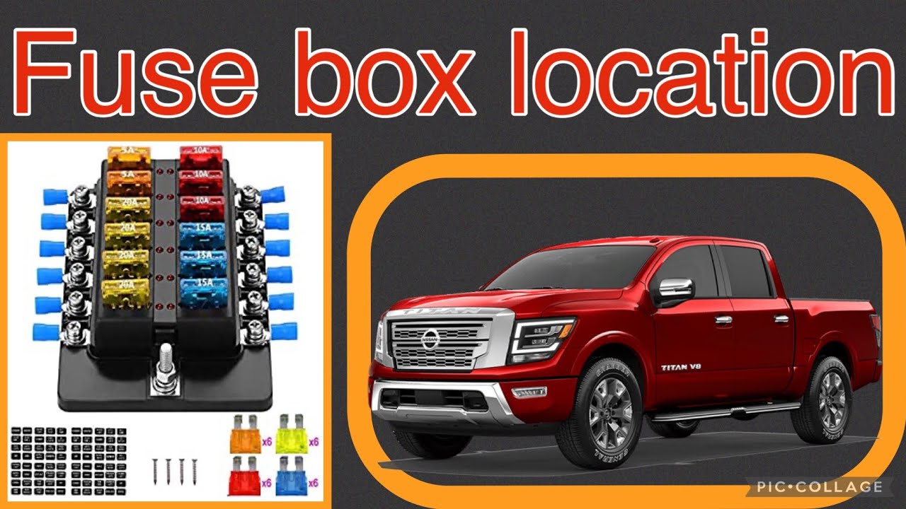
2016 Nissan Titan Xd Fuse Box Diagram
The 2016 Nissan Titan XD is a beast of a truck, and like any complex machine, understanding its electrical system is crucial for maintenance, repairs, and even some modifications. The fuse box diagram is your key to navigating this system. Whether you're troubleshooting a malfunctioning component, planning to add aftermarket accessories, or just want to gain a deeper understanding of your truck, this guide will walk you through the intricacies of the 2016 Titan XD's fuse box.
Purpose of the Fuse Box Diagram
The fuse box diagram serves several vital purposes:
- Troubleshooting Electrical Problems: When an electrical component fails, the fuse box is the first place to check. The diagram helps you quickly locate the fuse associated with the malfunctioning system.
- Performing Repairs: Knowing the fuse layout is essential when replacing faulty fuses or wiring.
- Adding Aftermarket Accessories: Installing new accessories, such as lights, amplifiers, or alarms, often requires tapping into the truck's electrical system. The diagram helps you identify appropriate circuits and choose suitable fuse ratings to protect the system.
- Understanding the Electrical System: Even if you're not actively working on your truck, the diagram provides valuable insight into how the electrical system is organized and how different components are interconnected.
Key Specs and Main Parts
The 2016 Nissan Titan XD typically has two main fuse box locations. The exact configurations can vary slightly depending on the trim level and options. These locations are:
- Interior Fuse Box: Usually located inside the cabin, often behind a panel on the driver's side dashboard or beneath the steering wheel. This box typically houses fuses for interior lighting, power windows, door locks, the infotainment system, and other cabin-related electrical components.
- Engine Compartment Fuse Box: Located under the hood, this box contains fuses for critical engine management systems, such as the fuel pump, ignition system, engine control module (ECM), and headlights. It also often includes relays, which are electromagnetic switches used to control higher-current circuits with low-current signals.
Each fuse box consists of several key parts:
- Fuse Box Housing: The plastic enclosure that protects the fuses and relays from the elements.
- Fuses: These are sacrificial devices designed to protect circuits from overcurrent. They contain a thin wire or strip of metal that melts and breaks the circuit if the current exceeds a specified limit. Fuses are rated in amperes (A), indicating the maximum current they can safely handle.
- Relays: Electromagnetically operated switches used to control circuits. They allow a low-current signal to switch a high-current circuit on or off.
- Connectors: These provide electrical connections between the fuse box and the vehicle's wiring harness.
- Fuse Puller: A small plastic tool used to safely remove and install fuses.
Understanding Fuse Box Diagram Symbols
Fuse box diagrams use symbols and abbreviations to represent different components and circuits. Understanding these symbols is crucial for interpreting the diagram accurately.
- Lines: Lines represent wires or electrical connections. Solid lines typically indicate direct connections, while dashed lines may indicate connections through a switch or relay.
- Colors: Wire colors are often indicated on the diagram using abbreviations (e.g., BLU for blue, RED for red, GRN for green). These colors help you identify the correct wires when working on the electrical system.
- Icons: Icons represent specific components, such as headlights, taillights, fuel pumps, and ECMs. The diagram should include a legend that explains the meaning of each icon. Common icons include a stylized lightbulb for lighting circuits, a small motor symbol for pumps, and a rectangular box with electronic symbols for control modules.
- Numbers: Numbers on the diagram correspond to the fuse or relay number in the fuse box.
- Amperage Ratings: Each fuse is labeled with its amperage rating (e.g., 10A, 15A, 20A). This indicates the maximum current the fuse can safely handle.
How It Works: The Electrical Flow
Understanding how electricity flows through the fuse box is key to troubleshooting problems effectively. Here's a simplified overview:
- Power Source: The battery is the primary power source for the vehicle's electrical system.
- Distribution: Power flows from the battery to the fuse boxes.
- Protection: Each circuit is protected by a fuse of the appropriate amperage rating. If a fault occurs (e.g., a short circuit), the fuse blows, interrupting the flow of current and preventing damage to the wiring and components.
- Component Activation: When a circuit is active (e.g., when you turn on the headlights), electricity flows through the fuse, through the wiring, and to the corresponding component, causing it to function.
- Relays: Some circuits are controlled by relays. A low-current signal from a switch or control module activates the relay, which then closes a high-current circuit to power the component.
Real-World Use: Basic Troubleshooting Tips
Here are some basic troubleshooting tips using the fuse box diagram:
- Identify the Problem: Determine which component is malfunctioning.
- Consult the Diagram: Locate the fuse associated with the malfunctioning component in the fuse box diagram.
- Inspect the Fuse: Remove the fuse using a fuse puller and visually inspect it. A blown fuse will have a broken filament or a dark, burned appearance.
- Replace the Fuse: Replace the blown fuse with a new fuse of the same amperage rating. Never use a fuse with a higher rating, as this could damage the wiring or components.
- Test the System: After replacing the fuse, test the component to see if it is working properly.
- If the Fuse Blows Again: If the new fuse blows immediately or soon after replacement, there is likely a short circuit or other electrical problem in the circuit. Further diagnosis is required to locate and repair the fault. This might require a multimeter to check for continuity and voltage readings.
Safety Considerations
Working with automotive electrical systems can be dangerous. Here are some important safety precautions:
- Disconnect the Battery: Before working on the electrical system, disconnect the negative terminal of the battery to prevent accidental short circuits.
- Use Proper Tools: Use insulated tools to avoid electric shock.
- Never Bypass Fuses: Never bypass a fuse with a wire or other conductive material. This can cause a fire or damage to the electrical system.
- Identify High-Risk Components: Be aware that some components, such as the airbag system, have their own backup power supplies. Disconnecting the battery may not completely disable these systems. Consult the service manual for proper procedures before working on these components.
- Relays controlling the fuel pump or ECM (Engine Control Module) are particularly sensitive. Mishandling or incorrect replacement can lead to serious engine problems.
Keep in mind that even a seemingly simple blown fuse can be a symptom of a more complex underlying issue. If you're not comfortable working on the electrical system yourself, it's best to consult a qualified mechanic.
We understand the importance of having access to reliable information when working on your vehicle. That's why we've compiled a comprehensive fuse box diagram for the 2016 Nissan Titan XD. You can download the diagram to have it readily available for your troubleshooting and repair needs.
Disclaimer: This information is intended for educational purposes only and should not be considered a substitute for professional advice. Always consult the vehicle's service manual for specific instructions and safety precautions.