
2017 Honda Pilot Trailer Wiring Harness
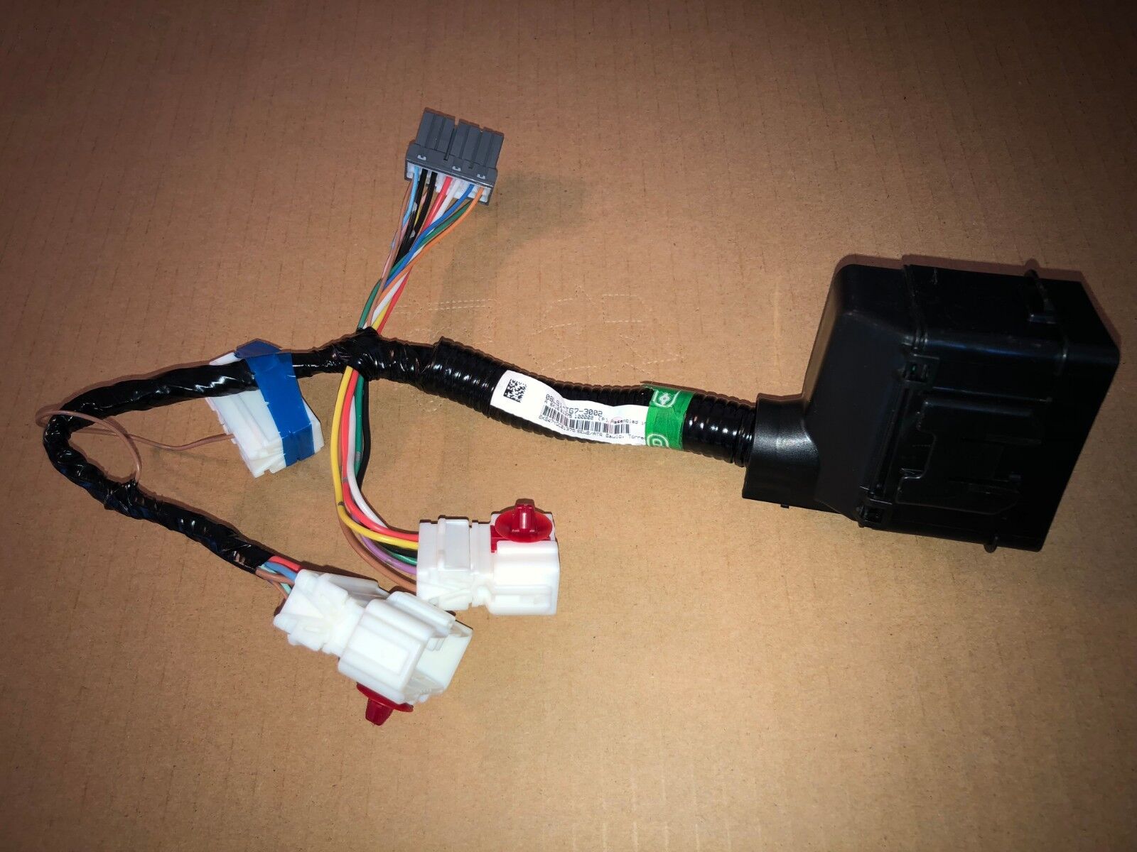
Alright, let's dive into the trailer wiring harness for the 2017 Honda Pilot. Understanding this system is crucial whether you're troubleshooting lighting issues, adding accessories, or just expanding your automotive knowledge. This walkthrough will equip you with the know-how to confidently tackle common problems and modifications related to your Pilot's trailer wiring.
Purpose of Understanding the Trailer Wiring Harness
Why bother understanding this complex web of wires? Several reasons:
- Troubleshooting Trailer Lights: The most common reason. If your trailer lights aren't functioning correctly (brake lights, turn signals, running lights), understanding the harness is essential for diagnosing the problem.
- Installation of Trailer Accessories: Adding electric trailer brakes, auxiliary power connections, or other trailer-related accessories requires a solid understanding of the wiring harness.
- Repairing Damaged Wiring: Road debris, corrosion, or accidental damage can compromise the wiring. Knowing the circuit layout allows for targeted repairs.
- Preventing Electrical Fires and Damage: Incorrect wiring can lead to short circuits, potentially damaging your vehicle's electrical system or even causing a fire.
- General Automotive Knowledge: Understanding electrical systems is a valuable skill for any car enthusiast.
Key Specs and Main Parts of the 2017 Honda Pilot Trailer Wiring Harness
The 2017 Honda Pilot, depending on trim and factory options, comes pre-wired for a trailer hitch and, typically, a 7-pin or 4-pin trailer connector. Let's break down the key components:
- Trailer Hitch Receiver: The physical mounting point for your trailer hitch. This isn't part of the wiring harness itself, but it's where the wiring ultimately connects.
- Wiring Harness Interface Connector (Vehicle Side): This is where the trailer wiring harness connects to your Pilot's existing wiring system. It's usually located near the rear of the vehicle, often behind a trim panel in the cargo area. Finding this connector is the first step.
- Trailer Wiring Harness (Adapter): This is the set of wires that connects to the vehicle-side connector and runs to the trailer connector. It typically includes a control module.
- Control Module (if equipped): Some harnesses include a control module, which isolates the trailer lights from the vehicle's lighting system. This is important to prevent overloading the vehicle's circuits and causing damage. This module will do things like convert two-wire brake/turn signals into separate signals for the trailer, and ensure the current draw doesn't overload the vehicle's electrical system.
- Trailer Connector (4-Pin or 7-Pin): This is the connector on the back of your vehicle that you plug your trailer into.
- 4-Pin Flat Connector: Provides basic lighting functions (ground, tail lights, left turn/brake, right turn/brake).
- 7-Pin Blade Connector: Offers more functionality, including ground, tail lights, left turn/brake, right turn/brake, reverse lights, electric brakes, and auxiliary power.
- Wiring Gauge: The thickness of the wires is critical. Typically, you'll see 16-gauge or 14-gauge wire used in trailer wiring harnesses. The smaller the number, the thicker the wire. Thicker wire is necessary for higher amperage circuits, such as electric brakes.
Understanding Wiring Diagram Symbols
Wiring diagrams use a standardized set of symbols to represent different components and connections. Here are some common symbols you'll encounter:
- Solid Lines: Represent wires. The thickness of the line might indicate the wire gauge, but it's not always consistent.
- Dashed Lines: Often represent shielded wires or wires that are part of a cable assembly.
- Circles: Can represent various things, depending on what is inside. It may contain a number which will indicate the wire identification.
- Rectangles: Often represent connectors or control modules.
- Ground Symbol (usually a series of horizontal lines decreasing in size): Indicates a connection to the vehicle's chassis ground.
- Colors: Wire colors are crucial for identification. Common colors include:
- White: Ground
- Brown: Tail Lights
- Yellow: Left Turn/Brake
- Green: Right Turn/Brake
- Blue: Electric Brakes (7-Pin)
- Black/Red: Auxiliary Power (7-Pin)
- Purple: Reverse Lights (7-Pin)
- Numbers: Numbers next to wires or connectors often indicate the circuit number or pin number.
How the Trailer Wiring Harness Works
The trailer wiring harness essentially taps into your vehicle's existing lighting circuits. Here's a simplified breakdown of how it works:
- Power Source: The harness draws power from the vehicle's battery, typically through a fuse-protected circuit.
- Signal Detection: The control module (if present) monitors the signals from your vehicle's brake lights, turn signals, and running lights.
- Signal Transmission: The control module then sends the appropriate signals to the trailer connector, activating the corresponding lights on the trailer.
- Isolation (with Control Module): The control module isolates the trailer lights from the vehicle's lights, preventing overloading and potential damage. Without a module, the trailer lights are directly connected to the vehicle's light circuits, increasing the risk of overloading.
Let's consider an example: When you press the brake pedal, your vehicle's brake light switch sends a signal to the brake lights. The trailer wiring harness control module detects this signal and sends power to the brake light pin on the trailer connector, activating the trailer's brake lights simultaneously. The same process applies to turn signals and running lights.
Real-World Use: Basic Troubleshooting Tips
Here are some common problems and troubleshooting steps:
- No Trailer Lights:
- Check the trailer connector for corrosion or damage. Clean the contacts and apply dielectric grease.
- Inspect the wiring on the trailer itself for loose connections or broken wires.
- Verify that the trailer's ground connection is secure. A poor ground is a common cause of lighting problems.
- Check the fuses in your vehicle's fuse box that are related to the trailer wiring. Consult your owner's manual for fuse locations.
- Test the pins on the trailer connector with a test light or multimeter to see if they are receiving power when the corresponding lights are activated in the vehicle.
- One or More Trailer Lights Not Working:
- Check the bulb in the affected light.
- Trace the wiring from the trailer connector to the light to identify any breaks or loose connections.
- All Trailer Lights Dim or Flickering:
- This often indicates a poor ground connection. Check the ground connections on both the trailer and the vehicle.
- Low voltage can also cause dimming. Check your vehicle's battery voltage and charging system.
- Vehicle Lights Affected When Trailer Is Connected:
- This is a sign that the trailer wiring is overloading the vehicle's circuits. This can be caused by faulty wiring on the trailer or a problem with the trailer wiring harness control module (if equipped).
Pro Tip: A trailer wiring tester is an invaluable tool for diagnosing trailer wiring problems. It allows you to quickly test the functionality of each pin on the trailer connector without having to connect a trailer.
Safety Considerations
Working with electrical systems carries inherent risks. Take these precautions:
- Disconnect the Battery: Before working on any electrical wiring, disconnect the negative terminal of your vehicle's battery to prevent short circuits and electrical shock.
- Use Proper Tools: Use insulated tools designed for automotive electrical work.
- Work in a Well-Lit Area: Good visibility is essential for identifying wires and making secure connections.
- Avoid Working in Wet Conditions: Water conducts electricity, increasing the risk of electrical shock.
- Fuses are your friends: Never bypass a fuse. Fuses protect the electrical system from overloads. If a fuse blows repeatedly, there's an underlying problem that needs to be addressed.
- Be Careful with Airbags: Avoid working near airbag modules without proper training and precautions. Accidental deployment can cause serious injury.
- The Control Module: The control module is a sensitive electronic component. Avoid dropping it or exposing it to excessive moisture.
Critical Note: Incorrect wiring can damage your vehicle's electrical system. If you're not comfortable working with electrical wiring, it's best to consult a qualified automotive electrician.
By understanding the 2017 Honda Pilot trailer wiring harness, you are better equipped to troubleshoot issues, perform upgrades, and maintain the safety and reliability of your vehicle and trailer. Remember to prioritize safety and consult a professional when needed.
We have access to the detailed wiring diagram for the 2017 Honda Pilot trailer wiring harness. It provides a comprehensive overview of the system, including wire colors, connector locations, and circuit layouts. It will prove invaluable to help you visualize the whole system. This document can be downloaded and used for future reference.