2017 Hyundai Tucson Fuse Box Diagram
For the experienced DIYer tackling electrical issues or planning modifications on their 2017 Hyundai Tucson, understanding the fuse box diagram is absolutely crucial. This article provides a detailed breakdown of the 2017 Tucson's fuse box, empowering you to diagnose problems, perform repairs, and even safely install aftermarket accessories. Forget blindly pulling fuses; let's get technical and demystify this critical component.
Purpose of the Fuse Box Diagram
Why bother with a fuse box diagram? Simple: it's your roadmap to the Tucson's electrical system. Here's why it matters:
- Troubleshooting Electrical Issues: A blown fuse is often the first sign of an electrical problem. The diagram pinpoints the exact fuse responsible for a specific circuit, like the radio, headlights, or power windows.
- Performing Repairs: Before attempting any electrical repair, identify and disconnect the relevant fuse to prevent short circuits and potential damage.
- Installing Aftermarket Accessories: Adding accessories like a dashcam, auxiliary lights, or a new sound system requires tapping into the electrical system. The diagram helps you identify suitable, safely fused circuits for power.
- Understanding Vehicle Systems: Studying the diagram provides a greater understanding of how different systems within the Tucson are interconnected and protected.
Key Specs and Main Parts of the Fuse Box
The 2017 Hyundai Tucson typically features two fuse box locations:
- Interior Fuse Box: Located inside the cabin, usually under the dashboard on the driver's side. This box primarily houses fuses for interior components like the radio, climate control, power windows, and interior lighting.
- Engine Compartment Fuse Box: Situated under the hood, near the battery and engine. This box protects crucial engine-related circuits like the fuel pump, ignition system, engine control unit (ECU), and exterior lighting.
Key components within the fuse box include:
- Fuses: These are the sacrificial elements designed to protect circuits from overcurrent. They consist of a thin wire or strip that melts and breaks the circuit when the current exceeds a specific amperage (A) rating.
- Relays: Electrically operated switches that control high-current circuits using a low-current signal. Relays are used for components like headlights, the starter motor, and the air conditioning compressor.
- Fuse Puller: A small plastic tool used to safely remove fuses without damaging them or the surrounding components.
- Spare Fuses: Often located within the fuse box itself, these are replacement fuses of various amperage ratings.
Understanding Fuse Box Diagram Symbols
Fuse box diagrams use a standardized set of symbols and conventions to represent electrical components and connections. Let's decipher some common ones:
- Lines: Solid lines represent electrical wires connecting components. Dashed lines may indicate ground connections or connections to other parts of the system.
- Colors: Wires are often color-coded in the diagram to match the actual wiring in the vehicle. Common colors include red (power), black (ground), and various other colors for specific circuits.
- Icons: Icons represent specific components, such as:
- Headlight Icon: Indicates the fuse for the headlights.
- Radio Icon: Represents the fuse for the radio or audio system.
- Window Icon: Shows the fuse for the power windows.
- Engine Icon: Represents fuses related to engine management and control.
- Amperage Rating: Each fuse is labeled with its amperage rating (e.g., 5A, 10A, 15A). This indicates the maximum current the fuse can handle before blowing.
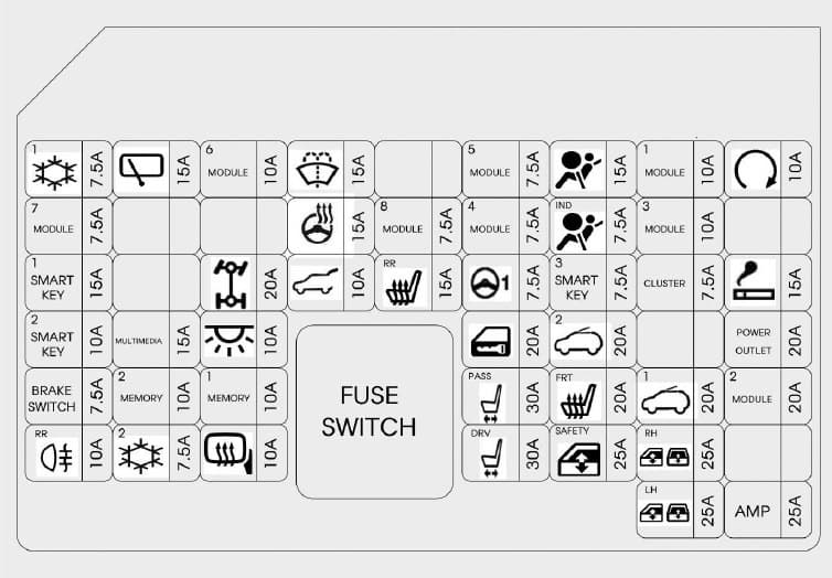
The diagram will often show a grid representing the physical layout of the fuses and relays within the box. Each position will be labeled with a number or letter combination corresponding to the list of components and their descriptions.
How It Works: The Electrical Flow
The fuse box acts as a central distribution point for electrical power within the vehicle. Power from the battery flows through the fuse box, and each fuse protects a specific circuit. When a component draws excessive current (e.g., due to a short circuit or a faulty component), the fuse in that circuit blows, interrupting the flow of electricity and preventing damage to other components.
Relays, on the other hand, act as switches. A small electrical signal from a control module (like the ECU) activates the relay, which then allows a larger current to flow through the circuit to power a high-demand component. This prevents the control module from being overloaded and allows for efficient control of high-power devices.
Real-World Use: Basic Troubleshooting Tips
Here's how to use the fuse box diagram for basic troubleshooting:
- Identify the Symptom: Determine which component is not working (e.g., the headlights, the radio, the power windows).
- Consult the Diagram: Locate the fuse box diagram (usually found in the owner's manual or online). Identify the fuse associated with the non-functional component.
- Inspect the Fuse: Use a fuse puller to remove the fuse. Visually inspect the fuse element. If the wire is broken or blackened, the fuse is blown. You can also use a multimeter set to continuity mode to test the fuse. A good fuse will show continuity; a blown fuse will not.
- Replace the Fuse: Replace the blown fuse with a new fuse of the same amperage rating. Using a fuse with a higher amperage rating can overload the circuit and cause damage.
- Test the Component: Turn on the component to see if it now works. If the fuse blows again immediately, there is likely a short circuit in the wiring or a faulty component that needs further investigation.
Important Note: If a fuse blows repeatedly, do not simply keep replacing it. This is a sign of a more serious underlying problem that needs to be addressed by a qualified mechanic.
Safety Considerations: Handling Risky Components
Working with the electrical system can be dangerous if proper precautions are not taken. Here are some safety tips:
- Disconnect the Battery: Before working on any electrical components, disconnect the negative terminal of the battery to prevent accidental short circuits and electric shock.
- Use Insulated Tools: Use tools with insulated handles to prevent electric shock.
- Avoid Working in Wet Conditions: Never work on the electrical system in wet or damp conditions.
- Identify High-Current Circuits: Be extra cautious when working around high-current circuits, such as the starter motor circuit, the alternator circuit, and the battery connections. These circuits can deliver a powerful electric shock.
- Consult a Professional: If you are not comfortable working on the electrical system, or if you encounter a problem that you cannot diagnose or repair, consult a qualified mechanic.
Some components protected by fuses can be particularly risky if tampered with incorrectly:
- Airbag System: The airbag system is a sensitive and potentially dangerous system. Do not attempt to repair or modify the airbag system unless you are specifically trained and equipped to do so.
- Anti-lock Braking System (ABS): The ABS is a critical safety system. Incorrect repairs or modifications can compromise its functionality.
- Engine Control Unit (ECU): The ECU controls many critical engine functions. Damaging the ECU can cause serious engine problems.
We have a high-resolution, downloadable PDF diagram of the 2017 Hyundai Tucson's fuse box. It provides a clear and detailed view of both the interior and engine compartment fuse box layouts, including fuse amperage ratings and component descriptions. This resource will greatly assist you in diagnosing and resolving electrical issues with your vehicle. Contact us to get your copy!