2017 Nissan Altima Fuse Box Diagram
So, you're looking at the fuse box diagram for a 2017 Nissan Altima, eh? Good on you! Understanding this seemingly cryptic chart is absolutely crucial for anyone who wants to perform basic electrical troubleshooting, install aftermarket accessories, or simply avoid an expensive trip to the mechanic. This article will be your detailed guide to navigating the intricacies of your Altima's fuse system.
Why You Need the Fuse Box Diagram
Let's cut to the chase. Why bother with this diagram? Here's the deal:
- Troubleshooting Electrical Problems: A blown fuse is the first suspect when an electrical component stops working. Without the diagram, you're just guessing. The diagram pinpoints the exact fuse related to the problematic circuit.
- Aftermarket Installations: Adding a new radio, lights, or any electrical accessory requires tapping into the car's electrical system. The diagram tells you which fuses protect various circuits, allowing you to safely choose a power source.
- Preventative Maintenance: Familiarizing yourself with the fuse layout can help you anticipate potential electrical issues and proactively inspect fuses.
- Cost Savings: Diagnosing and replacing a blown fuse yourself is far cheaper than a shop visit.
- Understanding Your Car: For the mechanically inclined, understanding the fuse system provides a deeper understanding of your vehicle's overall electrical architecture.
Key Specs and Main Parts
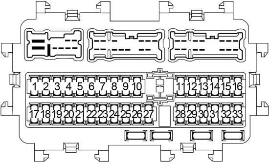
The 2017 Altima typically has two fuse box locations. The most important one is the Interior Fuse Box, usually located under the dashboard on the driver's side. The second location is the Engine Compartment Fuse Box, situated near the battery under the hood. Each fuse box serves a different purpose and houses different types of fuses and relays.
- Interior Fuse Box: This box protects circuits related to interior components like the radio, instrument panel, power windows, power locks, and interior lighting.
- Engine Compartment Fuse Box: This box handles circuits for engine management, headlights, windshield wipers, cooling fan, and other essential functions related to the engine and vehicle operation.
- Fuses: These are the sacrificial links in your electrical system. They're designed to melt and break the circuit if the current exceeds a safe level, protecting sensitive components from damage. Fuses are rated in Amperes (Amps), indicating the maximum current they can handle. Common fuse sizes are 5A, 7.5A, 10A, 15A, 20A, 25A, and 30A.
- Relays: These are electromechanical switches that control high-current circuits using a low-current signal. Relays are used for components that draw a lot of power, such as headlights, the starter motor, and the horn. A relay consists of a coil, which when energized by a small current, creates a magnetic field and pulls a set of contacts to switch the larger current circuit.
- Fuse Puller: A small plastic tool (often found in one of the fuse boxes) used to safely remove fuses without damaging them.
Decoding the Fuse Box Diagram: Symbols, Lines, and Colors
The fuse box diagram is essentially a map of the electrical circuits in your car. Understanding its symbology is critical.
- Lines: Lines represent electrical circuits. They connect the fuse to the component it protects.
- Fuse Numbers/Labels: Each fuse location is assigned a number or label (e.g., "F15," "Radio"). The diagram will have a legend linking these numbers to the specific component the fuse protects.
- Symbols: The diagram uses symbols to represent different electrical components. Common symbols include:
- Light Bulb: Represents headlights, taillights, interior lights, etc.
- Motor: Represents motors for power windows, windshield wipers, etc.
- Coil: Represents relays or solenoids.
- Speaker: Represents the audio system.
- Battery: Represents the battery.
- Colors (Sometimes): Some diagrams use different colors to indicate the Amperage rating of the fuse. For example, red might indicate a 10A fuse, while blue indicates a 15A fuse. Important: Always double-check the Amperage rating printed on the fuse itself, even if the diagram uses color-coding.
How It Works: Protecting the Electrical System
The fuse system is designed to prevent damage to your car's electrical components. Think of a fuse as a weak link in a chain. If the current in a circuit exceeds the fuse's rating, the fuse wire melts, breaking the circuit and stopping the flow of electricity. This prevents the excessive current from reaching the protected component, which could cause overheating, fire, or other damage. This is called Overcurrent Protection.
When a fuse blows, it's a sign that something is wrong. It could be a short circuit (a direct connection between the positive and negative wires), an overloaded circuit (too many devices drawing power from the same circuit), or a faulty component.
Real-World Use: Basic Troubleshooting
Here's a simple troubleshooting scenario:
Problem: Your radio stops working.
- Consult the Diagram: Locate the Interior Fuse Box diagram (we have the file ready for you to download). Find the fuse labeled "Radio" or "Audio System."
- Inspect the Fuse: Use a fuse puller to remove the fuse. Hold it up to the light and look for a broken filament inside. A good fuse will have a continuous filament.
- Replace the Fuse: If the fuse is blown, replace it with a new fuse of the exact same Amperage rating. Using a fuse with a higher Amperage rating can be dangerous and could cause damage to the circuit.
- Test the Radio: Turn on the radio to see if it works.
- If the Fuse Blows Again: If the new fuse blows immediately, there's a short circuit or overload in the radio circuit. Further diagnosis, potentially by a professional, is needed to find the root cause of the problem.
Safety First: Handling Risky Components
Working with electrical systems involves inherent risks. Here are some safety precautions:
- Disconnect the Battery (Recommended): Before working on any electrical component, disconnecting the negative terminal of the battery is the safest approach. This eliminates the risk of accidental shorts. At a minimum, make sure the ignition is turned off.
- Never Replace a Fuse with a Higher Amperage Rating: This is extremely dangerous. The circuit is designed to handle a specific current. Using a higher-rated fuse bypasses the protection mechanism and can lead to overheating, fire, and component damage.
- Avoid Working in Wet Conditions: Water and electricity don't mix. Work in a dry environment.
- Proper Tools: Use a fuse puller to avoid damaging the fuse or the fuse box terminals.
- If in Doubt, Seek Professional Help: If you're uncomfortable working with electrical systems, or if you're unable to diagnose the problem, consult a qualified mechanic.
- High Current Fuses: Be extra careful around the main fuses located near the battery. These protect the entire vehicle's electrical system and carry very high currents. Incorrect handling could be dangerous.
We have the 2017 Nissan Altima Fuse Box Diagram available for download. This detailed diagram will be a valuable resource for any electrical work you plan to undertake on your vehicle.