
2017 Nissan Pathfinder Engine Diagram
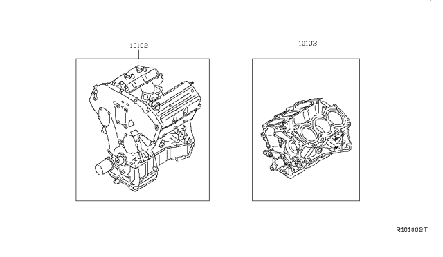
The 2017 Nissan Pathfinder is a popular SUV known for its reliability and family-friendly features. As a DIY mechanic or experienced car owner, having a solid understanding of its engine and its components is crucial for proper maintenance, repairs, and even potential modifications. This article focuses on deciphering the engine diagram of the 2017 Nissan Pathfinder, providing you with the knowledge to navigate its intricacies and tackle common issues. And just to let you know upfront - we've got the complete engine diagram file ready for download if you need it!
Purpose of Understanding the Engine Diagram
Why bother with an engine diagram? It's not just a pretty picture; it's a roadmap to your Pathfinder's powerplant. Understanding the diagram allows you to:
- Diagnose Issues Accurately: Pinpointing the source of a problem becomes much easier when you can visualize how different components interact.
- Perform Repairs Efficiently: Knowing the location and function of each part streamlines the repair process, saving you time and frustration.
- Plan Modifications Safely: If you're considering upgrades, the diagram helps you understand the impact of changes on other systems.
- Order the Right Parts: Accurate part identification prevents costly mistakes.
- General Knowledge: It's simply beneficial to understand how your vehicle operates.
Key Specs and Main Parts
The 2017 Nissan Pathfinder primarily came with a 3.5-liter VQ35DD V6 engine. This engine is part of Nissan's VQ engine family, known for its smooth power delivery and relative reliability. Key specs include:
- Displacement: 3.5 liters (3498 cc)
- Configuration: V6 (Six cylinders arranged in a V-shape)
- Aspiration: Naturally aspirated (no turbocharger or supercharger)
- Fuel Delivery: Direct Injection (explained later)
- Horsepower: Around 284 hp (horsepower can vary slightly based on trim and model year specifics, always consult your VIN).
- Torque: Around 259 lb-ft.
Key engine components you'll find on the diagram include:
- Cylinder Block: The engine's foundation, housing the cylinders, pistons, and crankshaft.
- Cylinder Head: Sits atop the cylinder block, containing the valves, camshafts, and combustion chambers. The 2017 Pathfinder uses dual overhead camshafts (DOHC), meaning there are two camshafts per cylinder head.
- Pistons: Move up and down within the cylinders, converting combustion energy into mechanical energy.
- Connecting Rods: Connect the pistons to the crankshaft.
- Crankshaft: Converts the reciprocating motion of the pistons into rotary motion, which is then transferred to the transmission.
- Intake Manifold: Distributes air to the cylinders.
- Exhaust Manifold: Collects exhaust gases from the cylinders.
- Fuel Injectors: Spray fuel into the cylinders (Direct Injection in this case).
- Spark Plugs: Ignite the air-fuel mixture in the cylinders.
- Throttle Body: Controls the amount of air entering the engine.
- Water Pump: Circulates coolant through the engine to regulate temperature.
- Oil Pump: Circulates oil through the engine to lubricate moving parts.
- Alternator: Generates electricity to power the vehicle's electrical system.
- Starter Motor: Cranks the engine to start it.
- Sensors: Various sensors like the Mass Airflow (MAF) sensor, Oxygen (O2) sensors, Crankshaft Position Sensor, and Camshaft Position Sensor monitor engine parameters and provide data to the Engine Control Module (ECM).
Decoding the Symbols
Engine diagrams aren't just drawings; they're coded representations of complex systems. Understanding the symbols is key:
- Lines: Solid lines typically represent fluid or gas lines (fuel, coolant, oil, vacuum). Dashed lines often indicate electrical wiring or control signals. The thickness of the line might indicate the diameter or capacity of the line.
- Colors: Colors often denote the type of fluid or signal being carried. For example, red might indicate fuel, blue might indicate coolant, and black might indicate ground. A color key is usually provided with the diagram.
- Icons: Specific icons represent different components. For example, a zigzag line represents a resistor, a circle with an "X" represents a pump, and a rectangle with a triangle represents a sensor. Again, consult the diagram's legend for specific icon definitions.
- Arrows: Show the direction of flow for fluids, gases, or electrical current.
- Abbreviations: Abbreviations are used extensively (e.g., ECM for Engine Control Module, MAF for Mass Airflow sensor, CKP for Crankshaft Position Sensor).
How It Works: A Simplified Overview
The 2017 Pathfinder's VQ35DD engine operates on the four-stroke combustion cycle:
- Intake: The piston moves down, drawing air into the cylinder through the intake valve. In a direct injection system, fuel isn't introduced during the intake stroke.
- Compression: The piston moves up, compressing the air-fuel mixture.
- Combustion: The spark plug ignites the compressed air-fuel mixture, creating an explosion that forces the piston down. The 2017 Pathfinder uses direct injection, meaning fuel is injected directly into the cylinder during the compression stroke (or sometimes just before ignition), rather than into the intake manifold. This allows for more precise fuel control and improved efficiency.
- Exhaust: The piston moves up, pushing the exhaust gases out of the cylinder through the exhaust valve.
The ECM controls various engine functions based on sensor inputs. For example, the MAF sensor measures the amount of air entering the engine, and the ECM uses this information to calculate the correct amount of fuel to inject. O2 sensors in the exhaust system monitor the air-fuel ratio and provide feedback to the ECM to optimize combustion. This entire process is carefully coordinated to provide the optimal performance, fuel economy, and emissions.
Real-World Use: Basic Troubleshooting Tips
Using the engine diagram, you can start troubleshooting common issues:
- Misfires: Locate the spark plugs and ignition coils. Check for damaged wiring or faulty components. If you know which cylinder is misfiring, you can focus your attention on that specific area of the diagram and the corresponding engine components.
- Vacuum Leaks: Trace the vacuum lines using the diagram to identify potential leak points. Common areas include connections to the intake manifold, brake booster, and other vacuum-operated devices.
- Coolant Leaks: Follow the coolant lines to identify potential leak sources, such as hoses, the water pump, or the radiator.
- Sensor Issues: If a specific sensor is throwing a code, use the diagram to locate the sensor and check its wiring and connections. Consult the diagram for the location of the ECM to check its connection points also.
Safety Precautions
Working on an engine can be dangerous. Always take these precautions:
- Disconnect the Battery: Always disconnect the negative battery cable before working on any electrical components.
- Work in a Well-Ventilated Area: Exhaust fumes and fuel vapors can be harmful.
- Use Proper Tools: Using the right tools for the job will prevent damage to the vehicle and injury to yourself.
- Be Careful of Hot Surfaces: The engine and exhaust system can get very hot. Allow them to cool down before working on them.
- Fuel System: The fuel system is under pressure and is highly flammable. Be extremely careful when working with fuel lines or fuel injectors. Relieve fuel pressure before disconnecting any fuel lines.
- High Voltage: Ignition coils and spark plugs carry high voltage. Avoid touching them while the engine is running or the ignition is on.
Important Note: This article provides a general overview. Always consult the specific repair manual for your 2017 Nissan Pathfinder for detailed instructions and specifications.
By understanding the 2017 Nissan Pathfinder engine diagram, you can confidently tackle a wider range of maintenance and repair tasks. Remember, start with a thorough understanding of the system, take safety precautions, and consult the repair manual for specific guidance. This approach will make you a more effective and informed DIYer.
Remember, we have the complete engine diagram file ready for download, just let us know!