2017 Nissan Sentra Fuse Box Diagram
The 2017 Nissan Sentra fuse box diagram is an invaluable resource for any owner looking to perform maintenance, troubleshoot electrical issues, or even customize their vehicle. Understanding this diagram empowers you to diagnose and resolve problems yourself, potentially saving significant money on mechanic fees and gaining a deeper understanding of your car's electrical system. We'll break down everything you need to know, from the basic components to practical troubleshooting techniques.
Purpose of the Fuse Box Diagram
Why is the fuse box diagram so important? Imagine your windshield wipers suddenly stop working, or your headlights go dim. The first place to check is often the fuse box. The diagram allows you to quickly identify the correct fuse associated with that specific circuit. Without it, you'd be blindly pulling fuses, potentially causing further damage or wasting time. More broadly, the diagram provides a roadmap to the electrical system, crucial for:
- Electrical Repairs: Precisely identifying faulty fuses or relays.
- Troubleshooting: Tracing circuits to pinpoint the source of an electrical problem.
- Accessory Installation: Safely tapping into existing circuits to power new accessories like dash cams or aftermarket lights.
- Learning: Developing a greater understanding of your vehicle's electrical layout and how various components interact.
Key Specs and Main Parts
The 2017 Sentra actually has *two* main fuse box locations:
- Interior Fuse Box: Located inside the cabin, typically under the dashboard on the driver's side. This fuse box primarily houses fuses for interior components like the radio, power windows, interior lights, and accessories.
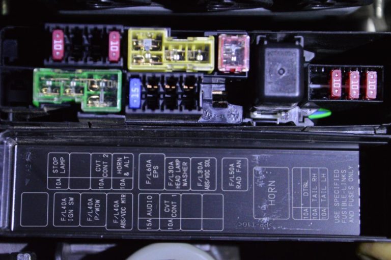
- Engine Compartment Fuse Box: Situated under the hood, usually near the battery. This box protects vital engine components, including the fuel pump, ignition system, cooling fan, and headlights.
Each fuse box contains:
- Fuses: These are sacrificial devices designed to protect circuits from overcurrent. When the current exceeds the fuse's rating, it blows, breaking the circuit and preventing damage to other components. Fuses are rated in amperes (amps, A), indicating the amount of current they can handle.
- Relays: These are electrically operated switches that allow a low-current circuit to control a high-current circuit. For example, a small switch on your dashboard activates a relay to power the high-current starter motor. Relays often protect sensitive switches from handling large currents.
- Fuse Puller: A small plastic tool used to safely remove fuses without damaging them. Usually located inside one of the fuse boxes.
- The Diagram Itself: Often printed on the inside of the fuse box cover or in the owner's manual. This is the key to understanding the fuse layout.
Understanding Fuse Box Symbols
The fuse box diagram utilizes specific symbols and abbreviations to represent different components and their functions. Here's a breakdown of common symbols:
- Lines: Solid lines represent the wiring connecting the fuses to the components they protect. Dashed lines may indicate ground connections or less critical wiring.
- Fuse Symbols: Typically represented by a rectangle with a zigzag line inside, often labeled with the amperage rating (e.g., "10A"). Sometimes shown as a simple rectangle.
- Relay Symbols: Usually depicted as a square or rectangle with internal components illustrating the coil and switch contacts.
- Abbreviations: Common abbreviations include:
- ACC: Accessory
- IGN: Ignition
- HTR: Heater
- P/W: Power Windows
- P/L: Power Locks
- ECU: Engine Control Unit
- ABS: Anti-lock Braking System
- Color Coding: While not always standardized, some diagrams use color coding to indicate the amperage rating of fuses (e.g., yellow for 20A, red for 10A).
The diagram will also show the location of each fuse and relay within the fuse box, often using a grid system (e.g., A1, B2, etc.) to pinpoint the exact position.
How It Works: A Simplified Explanation
Imagine a simple circuit powering a light bulb. The power source (battery) sends electricity through a wire to the fuse box. Inside the fuse box, the wire passes through a fuse. From the fuse, the wire continues to the light bulb and then back to the battery, completing the circuit. If, for any reason, the current flowing through the circuit becomes too high (e.g., due to a short circuit), the fuse's thin filament melts, breaking the circuit and stopping the flow of electricity. This prevents the light bulb and the wiring from overheating and potentially causing a fire. The fuse is therefore a circuit protection device.
Relays work similarly, but they act as remotely controlled switches. A low-current signal from a switch on the dashboard energizes the relay's coil. This magnetic field then pulls the relay's contacts together, closing the high-current circuit and allowing power to flow to the intended component (e.g., the starter motor).
Real-World Use: Basic Troubleshooting
Here's how to use the fuse box diagram for basic troubleshooting:
- Identify the Problem: Note the specific component that is malfunctioning (e.g., power windows, radio, headlights).
- Consult the Diagram: Locate the fuse or relay associated with that component in the diagram. Remember to check *both* the interior and engine compartment fuse boxes.
- Inspect the Fuse: Use the fuse puller to carefully remove the fuse. Visually inspect it for a broken filament. A blown fuse will have a clear break in the wire inside.
- Test the Fuse: For a more accurate test, use a multimeter set to continuity mode. Touch the probes to each end of the fuse. If the multimeter beeps or shows a low resistance value, the fuse is good. If it shows no continuity (open circuit), the fuse is blown.
- Replace the Fuse: Replace the blown fuse with a new fuse of the *exact same amperage rating*. Using a fuse with a higher rating can overload the circuit and cause damage.
- Test the Component: After replacing the fuse, test the component to see if the problem is resolved.
If the fuse blows again immediately after replacement, there is likely a short circuit or other underlying electrical problem in the circuit. Further diagnosis by a qualified technician may be necessary.
Safety Considerations
Working with electrical systems can be dangerous. Keep these safety precautions in mind:
- Disconnect the Battery: Before working on any electrical components, disconnect the negative (-) terminal of the battery to prevent accidental short circuits.
- Use the Correct Fuse Rating: Always replace a blown fuse with a fuse of the *exact same amperage rating*. Using a higher-rated fuse can bypass the circuit protection and lead to overheating, fires, or damage to components.
- Avoid Wet Conditions: Never work on electrical systems in wet or damp environments.
- High-Risk Components: Be particularly cautious around high-current circuits like the starter motor, alternator, and fuel pump. These circuits can deliver a significant electrical shock.
- If Unsure, Seek Professional Help: If you are not comfortable working with electrical systems, consult a qualified mechanic.
Understanding the 2017 Nissan Sentra fuse box diagram is a crucial skill for any DIY car enthusiast. With this guide, you'll be well-equipped to troubleshoot electrical problems, install accessories, and gain a deeper understanding of your vehicle's electrical system. Remember to prioritize safety and always consult a professional if you are unsure about any procedure.
We have a high-resolution version of the 2017 Nissan Sentra fuse box diagram available for download. Please refer to the resources section of our website for access to this file. This detailed diagram will provide you with a clear and comprehensive visual aid for your electrical troubleshooting and maintenance needs.