2017 Nissan Versa Fuse Box Diagram
The 2017 Nissan Versa, like any modern vehicle, relies heavily on a complex electrical system. Managing and understanding this system requires knowing your way around the fuse box. This article provides a detailed breakdown of the 2017 Nissan Versa fuse box diagram, empowering you to perform basic troubleshooting, repairs, and even safely add aftermarket accessories. We have the complete diagram, and you can download it from the link provided at the end of this article.
Why Understanding Your Fuse Box Matters
The fuse box is the central hub for electrical protection in your Versa. Fuses are sacrificial components designed to protect more expensive and vital systems from overcurrent damage. A blown fuse indicates an issue within the circuit it protects. Knowing the fuse box layout allows you to:
- Diagnose Electrical Problems: Quickly identify and replace blown fuses, resolving issues like non-functioning lights, accessories, or even starting problems.
- Perform Safe Modifications: When adding aftermarket accessories (like an aftermarket stereo or auxiliary lights), you need to tap into the vehicle's electrical system safely. Understanding the fuse box lets you find appropriate circuits and protect them with appropriately sized fuses.
- Avoid Costly Repairs: Simple fuse replacements can often be handled at home, saving you money on diagnostic fees and labor costs at a repair shop.
- Gain a Deeper Understanding of Your Vehicle: Familiarizing yourself with the electrical system improves your overall understanding of how your car functions.
Key Specs and Main Parts of the 2017 Versa Fuse Box
The 2017 Nissan Versa typically features two main fuse box locations:
- Interior Fuse Box: Located inside the cabin, usually beneath the dashboard on the driver's side or behind the glove box. This fuse box primarily protects circuits related to interior components like the radio, lights, power windows, and climate control system.
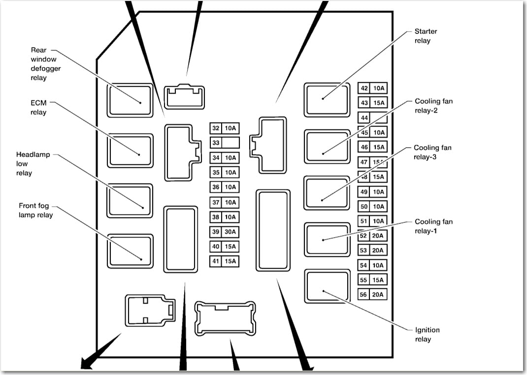
- Engine Compartment Fuse Box: Situated in the engine bay, often near the battery. This fuse box protects circuits associated with critical engine components, headlights, anti-lock braking system (ABS), and other essential systems.
Key Components:
- Fuses: The heart of the system. These small, inexpensive components contain a thin wire filament that melts and breaks the circuit when excessive current flows through it. Fuses are rated in amperes (amps), indicating the maximum current they can handle. The 2017 Versa uses various fuse types, including blade-type (ATO/ATC), mini-blade, and possibly cartridge fuses.
- Relays: Electrically operated switches that control higher-current circuits using a low-current signal. Relays are commonly used for headlights, starter motors, and other high-power components.
- Fuse Box Housing: The plastic enclosure that houses the fuses and relays. It provides physical protection and often includes a diagram indicating the function of each fuse and relay.
- Terminal Blocks: Connection points for wires entering and exiting the fuse box.
- Fuse Puller: A small plastic tool (often included in the fuse box) designed to safely remove and install fuses without damaging them or yourself.
Decoding the Fuse Box Diagram: Symbols and Meanings
The fuse box diagram is your roadmap to the electrical system. Here's how to interpret common symbols and conventions:
- Lines: Represent electrical circuits or wiring. Thicker lines may indicate higher current-carrying capacity.
- Colors: Wires are color-coded to help identify circuits. Refer to the wiring diagram for the specific color codes used in the 2017 Versa. Common colors include red (power), black (ground), and various colors for signal and control wires.
- Icons: Pictorial representations of the components protected by each fuse. Common icons include:
- Lightbulb: Indicates a fuse for a lighting circuit (headlights, taillights, interior lights).
- Radio: Represents the radio or infotainment system.
- Fan: Signifies the climate control system blower motor.
- Horn: Indicates the horn circuit.
- Cigarette Lighter/Power Outlet: Represents the power outlet circuit.
- Window: Represents the power windows.
- Amperage Rating: A number printed on the fuse itself, indicating its current capacity. This is crucial for replacing fuses; always use the correct amperage rating. Using a fuse with a higher amperage can damage the circuit it's supposed to protect.
- Relay Symbols: Relays are typically represented by a square or rectangle with internal markings indicating the coil and contacts.
How the Fuse Box Works: A Simplified Explanation
Imagine the electrical system as a network of roads. The battery is the power source, and the wires are the roads that carry electricity to various components (lights, radio, etc.). The fuse box acts as a central control point with miniature toll booths (fuses) on each road. Each toll booth is designed to allow a specific amount of traffic (current) to pass through. If the traffic exceeds the limit (overcurrent), the toll booth collapses (the fuse blows), preventing further damage to the road (the circuit).
When a circuit experiences a short circuit or overload, the current flowing through it increases dramatically. This excessive current heats the fuse element, causing it to melt and break the circuit. This interruption prevents the overcurrent from reaching and damaging the protected component.
Real-World Use: Basic Troubleshooting Tips
Here's how to use the fuse box diagram for troubleshooting:
- Identify the Problem: Determine which component is not working (e.g., the radio is dead, the headlights are out).
- Consult the Diagram: Locate the fuse associated with the non-functional component in the fuse box diagram.
- Inspect the Fuse: Visually inspect the fuse. A blown fuse will typically have a broken filament or a dark, burned appearance.
- Test the Fuse: Use a multimeter to test the fuse for continuity. Set the multimeter to the continuity setting (often indicated by a beep sound). Place the probes on each end of the fuse. If the multimeter beeps, the fuse is good. If it doesn't beep, the fuse is blown.
- Replace the Fuse: Replace the blown fuse with a new fuse of the same amperage rating.
- Test the Component: After replacing the fuse, test the component to see if it's now working.
- If the Fuse Blows Again: If the new fuse blows immediately or shortly after replacement, it indicates a more serious problem in the circuit, such as a short circuit. Further diagnosis is required, and it's recommended to consult a qualified mechanic.
Safety First: Risky Components and Precautions
Working with electrical systems involves inherent risks. Here are some crucial safety precautions:
- Disconnect the Battery: Before working on the fuse box, always disconnect the negative terminal of the battery to prevent accidental short circuits.
- Never Replace a Fuse with a Higher Amperage: This can bypass the circuit protection and lead to serious damage or even a fire.
- Avoid Touching Exposed Wires: Even with the battery disconnected, some capacitors may hold a charge.
- Work in a Well-Lit Area: Ensure adequate lighting to clearly see the fuse box and wiring.
- Use Proper Tools: Use a fuse puller to remove fuses and avoid using metal objects that could cause a short circuit.
- Be Aware of High-Current Circuits: Circuits associated with the starter motor, alternator, and ABS are high-current and potentially dangerous. Exercise extreme caution when working near these components.
Remember, while replacing a fuse is a simple task, diagnosing complex electrical problems requires specialized knowledge and equipment. If you are unsure about any aspect of the electrical system, it's always best to consult a qualified mechanic.
We have the complete 2017 Nissan Versa fuse box diagram available for download. You can access it [link to diagram]. Use it responsibly and safely!