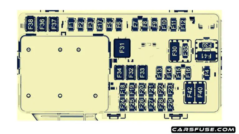
2018 Chevy Traverse Fuse Box Diagram
Understanding the fuse box diagram for your 2018 Chevy Traverse is crucial for a variety of reasons. Whether you're troubleshooting electrical issues, planning aftermarket modifications, or simply wanting a deeper understanding of your vehicle's systems, knowing how to interpret this diagram is an invaluable skill. It allows you to safely diagnose and address problems without potentially damaging sensitive electrical components.
Why You Need This Diagram
The 2018 Chevy Traverse fuse box diagram isn't just a piece of paper; it's a roadmap to your vehicle's electrical system. It serves several key purposes:
- Troubleshooting Electrical Problems: When a component stops working, a blown fuse is a prime suspect. The diagram helps you quickly locate the correct fuse associated with that component.
- Planning Aftermarket Modifications: Adding accessories like lights, amplifiers, or a dashcam requires understanding the vehicle's existing electrical circuits. The diagram helps you identify safe and appropriate points to tap into power.
- General Vehicle Understanding: For the mechanically inclined, the fuse box diagram provides a valuable overview of the electrical system's architecture and how different components are interconnected.
- Preventing Further Damage: Replacing a blown fuse with one of a higher amperage can overload the circuit and cause significant damage. The diagram specifies the correct amperage rating for each fuse.
Key Specs and Main Parts
The 2018 Chevy Traverse, like many modern vehicles, typically has multiple fuse boxes. The most important ones are usually located:
- Under the Hood (Engine Compartment): This box generally houses fuses and relays for critical engine and drivetrain components, such as the fuel pump, ignition system, and cooling fan.
- Inside the Cabin (Instrument Panel): This box typically controls fuses and relays for interior components like the radio, lights, power windows, and climate control system. Its exact location might vary, often found behind a small access panel on the dashboard, or near the footwell.
The diagram itself will typically include the following information for each fuse:
- Fuse Number or Identifier: A unique number or label that corresponds to a specific fuse location in the fuse box.
- Amperage Rating: The maximum current (measured in Amperes or Amps) that the fuse can handle before it blows. This is usually printed on the fuse itself and indicated on the diagram. Common ratings include 5A, 10A, 15A, 20A, 25A, 30A, and 40A.
- Protected Component or Circuit: A description of the component or circuit that the fuse protects. For example, "Radio," "Headlights (Left)," or "Fuel Pump Relay."
- Fuse Type: While most fuses in modern vehicles are blade-type fuses (ATO or Mini ATO), the diagram might specify the specific fuse type required.
Understanding the Symbols
Fuse box diagrams use standardized symbols to represent different components and connections. While specific symbols may vary slightly between manufacturers, here are some common examples:
- Solid Lines: Represent electrical wires or conductors.
- Dashed Lines: May indicate connections that are optional or only present in certain vehicle configurations.
- Rectangles: Typically represent fuses or relays.
- Circles: Can represent various sensors or electrical components.
- Ground Symbol (Usually three horizontal lines decreasing in length): Indicates a connection to the vehicle's chassis ground.
- Relay Symbol (Coil and Switch): A more complex symbol indicating a relay, which is an electrically operated switch used to control high-current circuits with a low-current signal.
Color coding can also be used, though less frequently on the diagram itself, but more so on the wiring harnesses within the vehicle. Knowing standard automotive wire color codes (e.g., Red for power, Black for ground) can be helpful.
How It Works: The Electrical Circuit and Fuse Protection
The fuse box is essentially a distribution point for electrical power throughout the vehicle. Power from the battery flows through the main wiring harness to the fuse box. From there, individual fuses protect each circuit that leads to a specific component. Each fuse is a sacrificial element in the circuit. It contains a thin wire or strip of metal designed to melt and break the circuit if the current exceeds the fuse's amperage rating.
Think of it like this: the fuse is a narrow bridge on a road. Normal traffic (normal electrical current) flows easily across the bridge. But if there's a sudden surge of traffic (excessive current due to a short circuit or overload), the bridge collapses (the fuse blows), preventing the surge from reaching the downstream components and causing damage. This overcurrent protection is crucial for the safety and reliability of the vehicle's electrical system.
Real-World Use: Basic Troubleshooting Tips
Here's a step-by-step approach to troubleshooting a blown fuse:
- Identify the Symptom: What component isn't working? (e.g., radio, headlights, power windows).
- Consult the Diagram: Use the 2018 Chevy Traverse fuse box diagram to locate the fuse associated with the affected component. Note the fuse number and amperage rating.
- Inspect the Fuse: Visually inspect the fuse. A blown fuse will typically have a broken filament visible through the clear plastic window. You can also use a multimeter in continuity mode to test the fuse. A good fuse will show continuity (a beep or a reading close to zero ohms), while a blown fuse will show no continuity (an open circuit).
- Replace the Fuse: Replace the blown fuse with a new fuse of the exact same amperage rating. Never use a fuse with a higher amperage rating, as this can overload the circuit and cause a fire.
- Test the Component: After replacing the fuse, test the affected component to see if it's working again.
- If the Fuse Blows Again: If the new fuse blows immediately or shortly after replacement, there's likely a short circuit or overload in the wiring or the component itself. Further diagnosis is needed to find the source of the problem. This might involve tracing the wiring harness, checking for damaged wires, or testing the component for shorts to ground. This may require more advanced diagnostic tools and knowledge.
Safety: Proceed with Caution!
Working with electrical systems can be dangerous. Always follow these safety precautions:
- Disconnect the Battery: Before working on any electrical component, disconnect the negative terminal of the battery to prevent accidental shorts.
- Use Proper Tools: Use insulated tools to avoid electric shock.
- Never Replace a Fuse with a Higher Amperage: This is extremely dangerous and can cause a fire. Always use the correct amperage rating specified in the diagram.
- Avoid Working in Wet Conditions: Water conducts electricity and increases the risk of electric shock.
- High-Current Circuits: Be especially careful around high-current circuits, such as those related to the starter motor, alternator, and battery. These circuits can deliver a significant shock.
Components like the starter motor, alternator, and airbag system often have dedicated fuses and relays. These are considered risky components and should only be handled by qualified technicians due to the potential for serious injury.
Disclaimer: This article provides general information about the 2018 Chevy Traverse fuse box diagram. Specific details may vary depending on the vehicle's trim level and options. Always consult the official service manual for your vehicle for the most accurate and up-to-date information.
We have a copy of the 2018 Chevy Traverse fuse box diagram available for download. Please contact us for access to the file.