2019 Ford F350 Fuse Box Diagram Under Hood
For the experienced DIY mechanic tackling electrical work on a 2019 Ford F350, understanding the under-hood fuse box diagram is absolutely critical. It's your roadmap to troubleshooting electrical issues, adding aftermarket accessories, and generally understanding the electrical architecture of your truck. Think of it as the electrical nervous system; damage one part, and you could affect a seemingly unrelated area. This guide will walk you through interpreting the diagram, understanding its components, and applying that knowledge to real-world scenarios.
Purpose of the Fuse Box Diagram
The fuse box diagram serves several key purposes:
- Troubleshooting: Quickly identify which fuse or relay controls a specific circuit. If your headlights aren't working, you can use the diagram to locate the headlight fuse and test it.
- Modification: When adding accessories like auxiliary lights, winches, or aftermarket sound systems, the diagram helps you identify suitable power sources and properly fuse your new circuits. This prevents overloading existing circuits and potentially causing a fire.
- Repair: Replacing a faulty fuse box? The diagram ensures you connect everything correctly, avoiding damage to sensitive electronic components.
- Understanding: Simply put, the diagram enhances your overall understanding of your truck's electrical system, empowering you to diagnose and fix issues yourself, saving time and money.
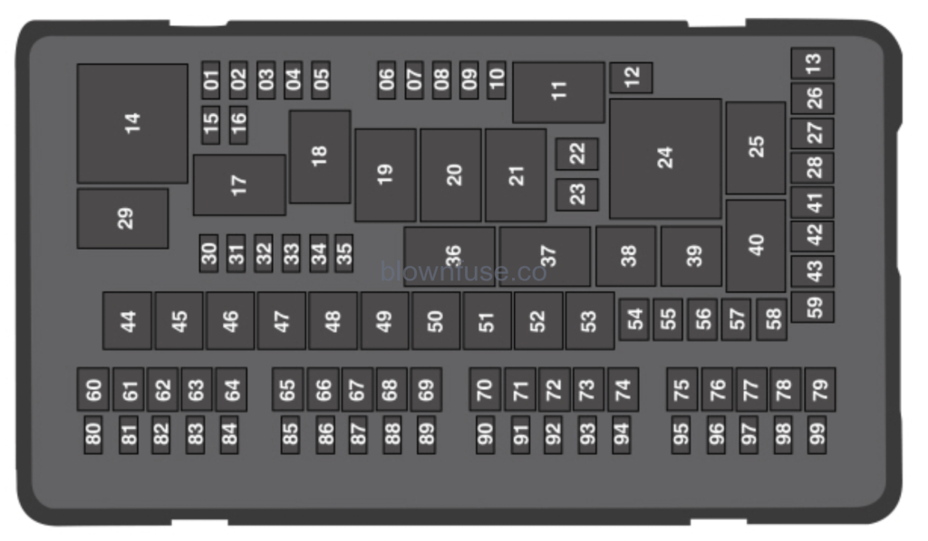
Key Specs and Main Parts of the 2019 F350 Under-Hood Fuse Box
The under-hood fuse box, also often referred to as the Battery Junction Box (BJB) or Power Distribution Box (PDB), houses fuses, relays, and sometimes diodes. In the 2019 F350, its specific location is typically on the driver's side of the engine compartment, near the battery. Ford often includes a diagram on the inside of the fuse box cover. However, these can be easily lost or become damaged. Having a readily available digital copy is invaluable.
Key components include:
- Fuses: These are sacrificial devices designed to protect circuits from overcurrent. They contain a thin wire that melts and breaks the circuit when the current exceeds a specific rating (measured in Amperes or Amps). Common fuse types in the F350 include blade fuses (ATO/ATC), mini-blade fuses, and cartridge fuses.
- Relays: These are electromechanical switches that use a small current to control a larger current. They are used to switch high-power circuits, like headlights, starters, and fuel pumps, without routing high current through the dashboard switches.
- Diodes: These are semiconductor devices that allow current to flow in only one direction. They are often used in circuits to prevent voltage spikes or reverse current flow, protecting sensitive electronic components.
- Bus Bars: These are conductive strips that distribute power from the battery to multiple fuses and relays.
Understanding the Symbols on the Fuse Box Diagram
The fuse box diagram uses specific symbols and conventions to represent different components and their connections. Learning to interpret these symbols is crucial for understanding the diagram.
- Lines: Solid lines represent wires connecting components. Dashed lines may indicate a ground connection or a control signal wire.
- Colors: Wires are often color-coded, and the diagram may indicate the color of each wire. For example, "RD/BK" indicates a red wire with a black stripe. Knowing the wire color can be immensely helpful when tracing circuits.
- Fuse Symbols: A fuse is typically represented by a wavy line inside a rectangle. The number next to the symbol indicates the fuse's amperage rating (e.g., "20A" means a 20-Amp fuse).
- Relay Symbols: A relay is usually represented by a coil symbol connected to a switch. The diagram may also indicate the relay's function (e.g., "Fuel Pump Relay").
- Ground Symbol: This symbol, resembling an inverted pyramid or a series of decreasing horizontal lines, indicates a connection to the vehicle's chassis ground.
Understanding Circuit Numbers: Each fuse and relay location typically has a unique identifier, such as "F1," "R3," or "Fuse 22." These identifiers are essential for referencing the correct component on the diagram.
How the Fuse Box Works: A Simplified Explanation
The fuse box acts as the central distribution point for electrical power in your F350. Power from the battery flows through the main power cables to the fuse box. Inside the fuse box, bus bars distribute this power to various fuses and relays.
Fuse Protection: Each circuit in the vehicle is protected by a fuse. If a short circuit or overcurrent condition occurs in a particular circuit (e.g., due to a faulty component or a wiring problem), the fuse for that circuit will blow, interrupting the flow of electricity and preventing damage to the wiring and components connected to that circuit. It's like a controlled weakness designed to fail before something more expensive does.
Relay Control: Relays allow low-current circuits (e.g., the dashboard switch for your headlights) to control high-current circuits (e.g., the headlights themselves). When you turn on the headlight switch, a small current flows through the relay coil, energizing it and closing the relay's contacts. This allows a high current to flow from the battery to the headlights, turning them on.
Real-World Use: Basic Troubleshooting Tips
Let's say your trailer running lights aren't working. Here's how you can use the fuse box diagram to troubleshoot the issue:
- Consult the Diagram: Locate the fuse box diagram (you can download a copy from us – see below!). Identify the fuse responsible for the trailer running lights. The diagram will likely label it with a description like "Trailer Tow Running Lights" or something similar.
- Locate the Fuse: Find the physical location of the identified fuse in the fuse box.
- Inspect the Fuse: Visually inspect the fuse. If the thin wire inside the fuse is broken or blackened, the fuse is blown and needs to be replaced.
- Test the Fuse: Even if the fuse looks okay, it's best to test it with a multimeter. Set the multimeter to continuity mode (often indicated by a beep symbol). Touch the multimeter probes to the two terminals of the fuse. If the multimeter beeps, the fuse is good. If it doesn't beep, the fuse is blown.
- Replace the Fuse: Replace the blown fuse with a new fuse of the same amperage rating. Never use a fuse with a higher amperage rating, as this can overload the circuit and cause a fire.
- Test the Circuit: After replacing the fuse, test the trailer running lights to see if they are working. If the fuse blows again immediately, there is likely a short circuit in the trailer wiring or the trailer lights themselves. Further investigation is required.
Other Common Issues: The diagram can also help diagnose issues with interior lights, power windows, door locks, and other electrical components. The process is the same: identify the relevant fuse or relay, inspect it, and replace it if necessary.
Safety Considerations: Working with Electrical Components
Working with your vehicle's electrical system can be dangerous if you're not careful. Here are some essential safety precautions:
- Disconnect the Battery: Before working on any electrical component, always disconnect the negative (-) terminal of the battery. This will prevent accidental short circuits and electrical shocks.
- Identify High-Risk Components: Be especially cautious when working with components associated with the airbag system (Supplemental Restraint System or SRS) and the anti-lock braking system (ABS). Incorrect handling of these components can cause serious injury or system malfunction. Consult a qualified technician if you are not comfortable working with these systems.
- Use Appropriate Tools: Use insulated tools and wear safety glasses to protect yourself from electrical shocks and flying debris.
- Never Bypass a Fuse: Never bypass a fuse by using a wire or other conductive material. This eliminates the circuit protection and can cause a fire.
- Double-Check Connections: Before reconnecting the battery, double-check all your connections to ensure they are secure and properly insulated.
High-Current Components: Be aware of circuits handling high currents, like the starter motor circuit or the alternator circuit. These circuits use heavier gauge wires and higher amperage fuses, and they can deliver a significant electrical shock if mishandled.
We understand the importance of having a reliable resource for your 2019 Ford F350 fuse box diagram. To assist you further, we have the complete, high-resolution diagram available for download. This file can be a lifesaver when you're in the middle of a repair or modification project. Click the link below to download:
(Link to download the 2019 Ford F350 Under-Hood Fuse Box Diagram)
Armed with this knowledge and the diagram, you'll be well-equipped to tackle electrical troubleshooting and modifications on your 2019 Ford F350 with confidence and safety. Remember to always prioritize safety and consult a qualified technician if you encounter any complex or unfamiliar issues. Good luck!