
2019 Nissan Frontier Fuse Box Diagram
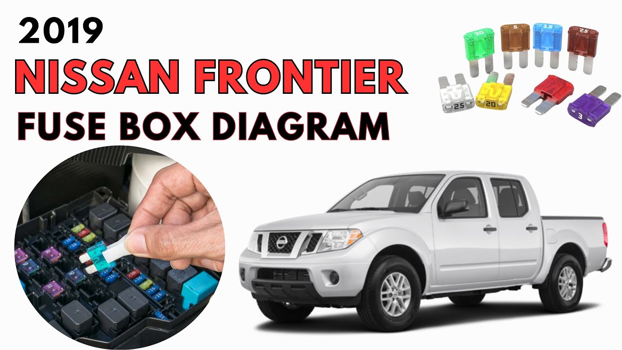
The 2019 Nissan Frontier, while a rugged and reliable truck, is still subject to electrical gremlins. Understanding its fuse box diagram is crucial for diagnosing and resolving electrical issues, adding aftermarket accessories, or simply deepening your understanding of your vehicle. This document will guide you through interpreting the 2019 Frontier's fuse box diagrams, focusing on their purpose, key components, symbol interpretation, operational principles, real-world application, and critical safety considerations. We'll assume you're familiar with basic automotive tools and procedures.
Purpose of the Fuse Box Diagram
The fuse box diagram is essentially a roadmap for your vehicle's electrical system. It provides a visual representation of each fuse and relay's location and function within the various fuse boxes. This is invaluable for several reasons:
- Troubleshooting Electrical Problems: When an electrical component fails (e.g., a taillight, radio, or power window), the first step is usually to check its corresponding fuse. The diagram pinpoints the exact fuse to inspect, saving you time and preventing unnecessary component replacements.
- Installing Aftermarket Accessories: Adding accessories like auxiliary lights, a new stereo system, or a trailer brake controller often requires tapping into the vehicle's electrical system. The diagram helps you identify suitable fuse locations for powering these devices safely, protecting both the accessory and your truck's electrical infrastructure.
- Understanding Vehicle Systems: Studying the fuse box diagram provides insight into how different electrical circuits are interconnected and protected. This knowledge enhances your overall understanding of your Frontier's electrical system.
- Preventing Further Damage: Identifying a blown fuse quickly can prevent further damage to components connected to that circuit. Ignoring a blown fuse might lead to short circuits or even fires under worst case scenario.
Key Specs and Main Parts of the Fuse Box
The 2019 Nissan Frontier typically has at least two primary fuse box locations:
- Interior Fuse Box: Usually located under the dashboard, often on the driver's side. This fuse box primarily houses fuses for interior components like the radio, interior lights, power windows, and climate control system.
- Engine Compartment Fuse Box: Situated in the engine bay, this fuse box protects vital engine-related systems, including the fuel pump, ignition system, headlights, and various sensors. It may also contain relays for heavier-duty functions.
Key components you'll find within these fuse boxes include:
- Fuses: These are the sacrificial elements in each circuit, designed to blow (open the circuit) when the current exceeds a specified limit. They come in various amperage ratings (e.g., 5A, 10A, 15A, 20A, 30A), indicated by a number printed on the fuse and often distinguished by color. The amperage rating indicates the maximum current the fuse can handle before it blows.
- Relays: These are electromechanical switches that control high-current circuits using a low-current signal. They're used to operate components like the headlights, starter motor, and air conditioning compressor. They are typically cube-shaped and can be easily pulled out.
- Fuse Puller: A small plastic tool included in the fuse box, used to safely remove and install fuses without damaging them or the fuse box.
- Fuse Box Cover: Provides protection for the fuses and relays and usually has a simplified diagram printed on the inside indicating the function of each fuse/relay.
Understanding Fuse Box Diagram Symbols
Fuse box diagrams use symbols to represent different components and functions. Here's a breakdown of common symbols:
- Lines: Lines represent the electrical circuits. Thicker lines often indicate higher current-carrying circuits.
- Rectangles or Squares: These typically represent fuses. The number inside or next to the rectangle indicates the fuse's amperage rating.
- Circles or Ovals: These may represent relays or other electronic components.
- Icons: Many diagrams use icons to represent the component protected by the fuse. For example, a headlight icon indicates a fuse for the headlights, a radio icon for the radio, etc. These icons vary in detail, but are generally intuitive.
- Colors: While not always consistent, wire colors indicated on some more detailed diagrams can help trace circuits. Refer to your vehicle's specific wiring diagrams (often found in service manuals) for accurate color-coding information.
- Acronyms: The diagrams often use acronyms to describe circuits, like "ECU" (Engine Control Unit), "ABS" (Anti-lock Braking System), or "A/C" (Air Conditioning).
It's important to remember that the diagram printed on the fuse box cover is a simplified version. A more detailed diagram can be found in your owner's manual or a dedicated repair manual.
How the Fuse Box Works
The fuse box acts as a central distribution and protection point for your vehicle's electrical system. Power from the battery is distributed to various circuits through the fuse box. Each circuit is protected by a fuse with a specific amperage rating.
Here's how it works:
- Normal Operation: When the electrical system is functioning correctly, current flows through the fuse. The fuse's internal element (a thin wire or strip) offers minimal resistance to the current flow.
- Overcurrent Condition: If a short circuit or overload occurs, the current in the circuit exceeds the fuse's amperage rating. This excessive current causes the fuse's element to heat up rapidly.
- Fuse Blows: The heat melts the fuse's element, breaking the circuit. This interrupts the flow of current, preventing damage to the protected component and the rest of the electrical system.
Relays, on the other hand, use a small current to control a larger current. For example, the headlight switch activates a relay that supplies power to the headlights. This prevents the headlight switch from having to handle the high current required by the headlights, protecting the switch from damage.
Real-World Use: Basic Troubleshooting Tips
Here's a simple troubleshooting scenario:
Problem: Your turn signals are not working.
- Consult the Diagram: Locate the fuse box diagram (either on the cover or in your manual). Identify the fuse labeled "Turn Signals" or a similar designation.
- Locate the Fuse: Find the physical location of that fuse within the fuse box.
- Inspect the Fuse: Remove the fuse using the fuse puller. Visually inspect the fuse. A blown fuse will have a broken or blackened element.
- Replace the Fuse: If the fuse is blown, replace it with a new fuse of the exact same amperage rating. Using a higher amperage fuse can damage the circuit.
- Test the System: Turn on the ignition and test the turn signals. If they still don't work, there may be a more serious issue (e.g., a faulty turn signal switch or wiring problem) requiring further diagnosis.
Important Notes:
- Always use the correct amperage fuse.
- If a fuse blows repeatedly, there's a problem in the circuit. Don't just keep replacing the fuse; investigate the underlying cause.
- Check the ground connections. Bad grounds are common causes of electrical issues.
Safety Considerations
Working with automotive electrical systems involves inherent risks. Here are some important safety precautions:
- Disconnect the Battery: Before working on the electrical system, disconnect the negative battery cable. This prevents accidental shorts and electrical shocks.
- Avoid Water: Never work on the electrical system in wet conditions.
- Be Careful with Airbags: The airbag system is electrically activated. Consult a service manual before working near airbag components. Airbags can deploy unexpectedly if mishandled.
- High-Current Components: The starter motor and alternator circuits carry very high currents. Exercise extreme caution when working with these components.
- Use Proper Tools: Use insulated tools to prevent electrical shocks.
Identifying a risky component is very easy in a fuse diagram. Usually components protected with a fuse rated 30A or more requires extra attention and knowledge. These are likely high current circuits and any shorting of these may cause sparks and fire.
By understanding the 2019 Nissan Frontier's fuse box diagram and following proper safety procedures, you can confidently tackle electrical repairs and modifications, saving time and money while enhancing your vehicle's functionality.
We have access to a detailed PDF file containing the 2019 Nissan Frontier fuse box diagram. If you'd like a copy, feel free to request it.