2020 Ram 1500 Chassis Right Side Wiring Harness
The right-side wiring harness of a 2020 Ram 1500 is the unsung hero that keeps a significant portion of your truck's electrical system functioning smoothly. Understanding this harness is crucial for anyone undertaking electrical repairs, modifications, or even just wanting to deepen their knowledge of their vehicle. This article will dissect the harness, explaining its purpose, components, how it works, and providing practical troubleshooting tips.
Why Understand the Right Side Chassis Wiring Harness?
Having a solid understanding of the 2020 Ram 1500's right-side chassis wiring harness is invaluable for several reasons:
- Repairing Electrical Issues: Diagnosing and fixing issues with lights, sensors, or other electrical components becomes much faster and more accurate when you can trace wires and understand their connections.
- Performing Modifications: Adding aftermarket accessories like lights, auxiliary power outlets, or towing setups often requires tapping into the existing wiring. Knowing which wires to tap into and how to do it safely is paramount.
- Preventing Costly Repairs: Early detection of wiring issues (like frayed wires or loose connections) can prevent more significant electrical problems down the road.
- Enhanced Vehicle Knowledge: Simply understanding how your truck's electrical system is structured gives you a better overall understanding of its operation and maintenance needs.
Key Specs and Main Parts of the Harness
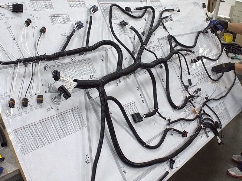
The 2020 Ram 1500 right-side chassis wiring harness is a complex assembly containing numerous wires, connectors, and protective coverings. Here are the key components:
- Wiring: The backbone of the harness. Wires are typically made of copper strands covered in insulation. Wire gauge (thickness) varies depending on the current-carrying capacity required. Larger gauge wires handle higher amperage loads.
- Connectors: These provide secure and weatherproof connections between different components and sections of the harness. Connectors often use locking mechanisms to prevent accidental disconnections. Types of connectors include:
- Inline Connectors: Join two wires directly.
- Multi-Pin Connectors: Connect several wires simultaneously to a component.
- Weatherpack Connectors: Designed to be weatherproof with rubber seals.
- Ground Points: The chassis serves as the common ground for the electrical system. Dedicated ground wires are attached to the chassis at specific points to ensure proper grounding. Poor grounding can cause a multitude of electrical issues.
- Fuses and Relays: Often integrated into the harness or located nearby in fuse boxes. Fuses protect circuits from overloads, while relays act as electrically controlled switches that allow low-current circuits to control high-current devices.
- Protective Looming/Sheathing: Plastic or fabric coverings protect the wires from abrasion, heat, and moisture. This is crucial for preventing shorts and damage to the wiring.
Understanding Wiring Diagram Symbols
A wiring diagram is essentially a map of the electrical system. Understanding the symbols is critical for interpreting the diagram correctly. Here are some common symbols you'll encounter:
- Solid Lines: Represent wires. The thickness of the line doesn't necessarily indicate wire gauge, but rather emphasizes the connection.
- Dotted Lines: May indicate shielded cables or grounding paths.
- Circles: Often represent connections or splices.
- Squares/Rectangles: Typically represent components like sensors, switches, relays, or control modules (e.g., the Body Control Module - BCM).
- Ground Symbol: A series of horizontal lines decreasing in length, indicating a connection to ground.
- Color Codes: Wires are color-coded to aid in identification. Common colors include Red (power), Black (ground), and various other colors for signals and control circuits. The wiring diagram will usually include a key explaining the color codes.
- Alphanumeric Codes: Each wire and connector is usually assigned a unique alphanumeric code (e.g., A123, Z456). These codes are essential for tracing wires and referring to specific connections in the wiring diagram.
Important: The wiring diagram will also denote the wire gauge and the circuit's function.
How the Right Side Chassis Harness Works
The right-side chassis wiring harness acts as a central distribution network for electrical power and signals. It connects various components, allowing them to communicate and function correctly. Here's a simplified explanation:
- Power Distribution: The harness receives power from the battery (usually through a fuse box or power distribution center) and distributes it to various components on the right side of the chassis.
- Signal Transmission: The harness transmits signals from sensors (e.g., wheel speed sensors, parking sensors) to control modules (e.g., ABS module, BCM). These signals provide information about the vehicle's operating conditions.
- Component Control: The harness carries signals from control modules to actuators (e.g., lights, motors, solenoids) to control their operation. For example, the BCM might send a signal through the harness to activate the right-side taillight.
- Grounding: The harness provides grounding paths for various components, ensuring a stable and reliable electrical circuit.
Example: Consider the right-side taillight. The harness provides power to the taillight bulb(s) and carries signals from the brake light switch, turn signal switch, and parking light switch to control the taillight's functions.
Real-World Use and Basic Troubleshooting
Here are some practical troubleshooting tips when dealing with the right-side chassis wiring harness:
- Start with the Basics: Before diving into the harness, check the fuses related to the circuit you're troubleshooting. A blown fuse is often the simplest solution.
- Visual Inspection: Carefully inspect the harness for any signs of damage, such as frayed wires, cracked insulation, corroded connectors, or loose connections. Pay particular attention to areas near exhaust components or where the harness passes through body panels.
- Use a Multimeter: A multimeter is an essential tool for diagnosing electrical problems. You can use it to check for voltage, continuity (a complete circuit), and resistance.
- Check for Voltage Drops: A voltage drop indicates a resistance in the circuit, which can be caused by a corroded connection or a damaged wire.
- Test for Continuity: Use a multimeter to test for continuity between two points on a wire. If there's no continuity, the wire is broken.
- Isolate the Problem: Try to isolate the problem to a specific section of the harness. Disconnect connectors and test each section individually to pinpoint the source of the issue.
- Refer to the Wiring Diagram: The wiring diagram is your roadmap. Use it to trace wires, identify connectors, and understand the circuit's operation.
Example: If your right-side taillight is not working, start by checking the taillight fuse. If the fuse is good, inspect the wiring harness near the taillight for any signs of damage. Use a multimeter to check for voltage at the taillight connector. If there's no voltage, trace the wire back to the fuse box, checking for continuity and voltage drops along the way.
Safety Considerations
Working with automotive electrical systems can be dangerous. Here are some essential safety precautions:
- Disconnect the Battery: Always disconnect the negative battery cable before working on the electrical system. This will prevent accidental shorts and electrical shocks.
- Use Proper Tools: Use insulated tools designed for automotive electrical work.
- Avoid Working in Wet Conditions: Water can conduct electricity, increasing the risk of electrical shock.
- Be Aware of Airbag Components: Airbag systems contain sensitive electronic components. Improper handling can trigger airbag deployment, causing serious injury. Consult the service manual for specific instructions on working around airbags.
- Be Cautious with High-Current Circuits: Circuits involving the starter motor, alternator, and battery can carry high currents. Exercise extreme caution when working on these circuits.
- Never Bypass Fuses: Fuses are designed to protect circuits from overloads. Bypassing a fuse can lead to overheating, fires, and damage to electrical components.
Important: Always consult the vehicle's service manual for specific safety procedures and wiring diagrams.
Downloadable Diagram
We have a detailed wiring diagram of the 2020 Ram 1500 Chassis Right Side Wiring Harness that you can download. This diagram will be invaluable for troubleshooting and repairs.
Disclaimer: Working on automotive electrical systems requires a certain level of skill and knowledge. If you are not comfortable performing these tasks, it is best to consult a qualified mechanic.