2024 Ford Bronco Auxiliary Switches Wiring Diagram
Alright, let's dive into the 2024 Ford Bronco auxiliary switches wiring diagram. Whether you're planning to wire up some off-road lights, a winch, or any other aftermarket electrical accessory, understanding this diagram is crucial. Consider this your go-to guide for tackling those electrical upgrades safely and effectively.
Purpose of the Auxiliary Switch Wiring Diagram
Why bother with this diagram? Well, it serves several key purposes:
- Repair and Maintenance: When things go wrong (and they often do with electrical systems), the diagram helps you trace circuits, identify faulty components (relays, fuses, wiring), and diagnose problems with the auxiliary switches themselves.
- Aftermarket Upgrades: This is the big one. The Bronco's auxiliary switches are designed to make adding accessories easy. The diagram shows you exactly how to tap into these circuits without causing shorts or frying your electrical system.
- Understanding Your Vehicle: Even if you're not planning any immediate upgrades, understanding the diagram gives you a deeper knowledge of your Bronco's electrical architecture. It's empowering!
- Safety: Proper wiring is paramount. Incorrect wiring can lead to fires, damage to your vehicle's computer systems (ECU/PCM), and potentially injury. The diagram helps you avoid these hazards.
Key Specifications and Main Parts
Let's break down the key specs and parts related to the auxiliary switches. While the exact amperage ratings might vary slightly depending on the Bronco trim level and options package, the fundamental components remain consistent. Always consult your owner's manual for the definitive specifications for *your* Bronco.
Auxiliary Switch Pack
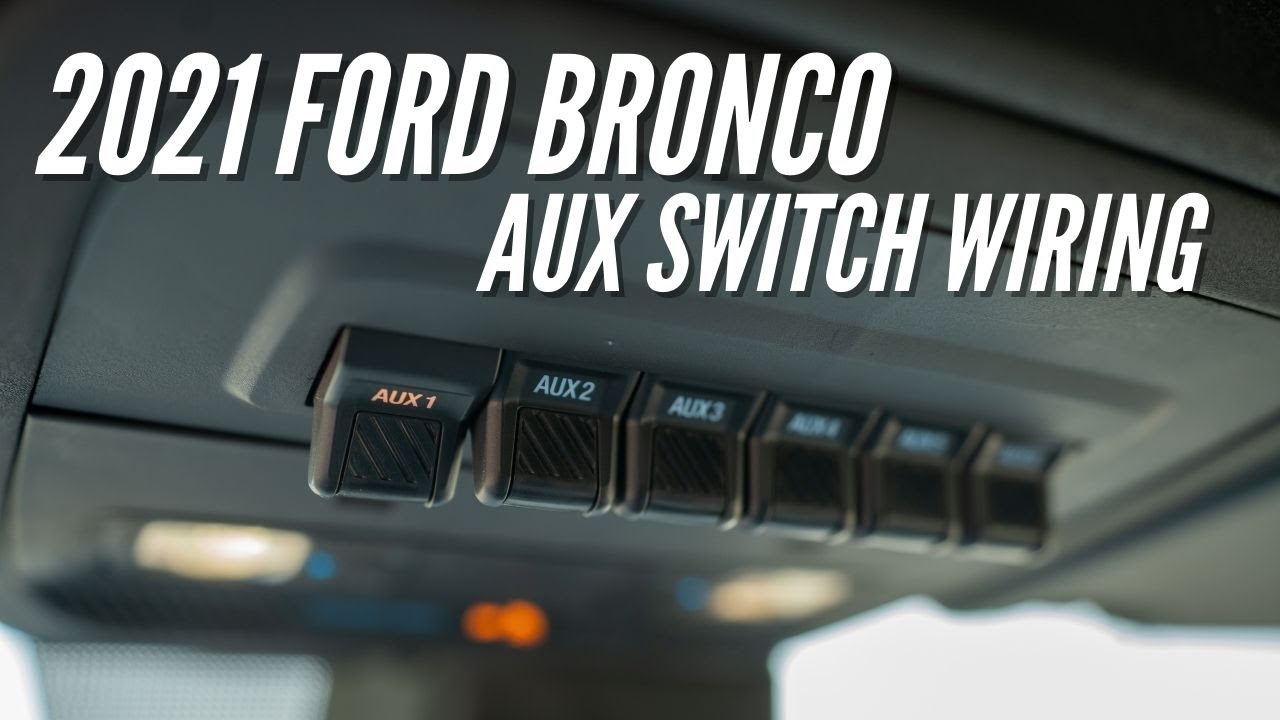
The auxiliary switch pack is usually located on the overhead console. It typically consists of six switches, numbered 1 through 6. These are low-current switches that control relays.
Relays
The *relays* are the workhorses of the system. They are electromagnetic switches that use a low-current signal from the auxiliary switch to control a high-current circuit powering your accessory. The relays are typically located in the engine compartment's relay box/power distribution box. Expect to find at least six relays associated with the auxiliary switches. Each relay has the following terminals:
- 30: Battery power input.
- 85: Ground connection for the relay coil.
- 86: Trigger wire from the auxiliary switch.
- 87: Normally open (N.O.) output to the accessory.
- 87a: (Sometimes present) Normally closed (N.C.) output, not usually used in aux switch applications.
Fuses
Each auxiliary switch circuit is protected by a fuse, typically located in the same power distribution box as the relays. These fuses are designed to protect the wiring and accessories from overcurrent conditions (short circuits, excessive load). The amperage rating of the fuse will dictate the maximum current that can be safely drawn by the accessory connected to that switch.
Wiring Harness
The *wiring harness* is the collection of wires that connect the auxiliary switches, relays, fuses, and accessories. These wires are color-coded for easy identification (more on that below).
Ground Points
Proper grounding is critical for any electrical circuit. The auxiliary switch circuits will have dedicated ground points, usually located on the chassis or body of the Bronco. Ensure these connections are clean and tight for optimal performance.
Understanding Wiring Diagram Symbols
Wiring diagrams use a standardized set of symbols to represent electrical components and connections. Here are some common symbols you'll encounter in the 2024 Bronco auxiliary switch wiring diagram:
- Solid Lines: Represent wires. The thickness of the line may (but often doesn't) indicate wire gauge (thickness).
- Dashed Lines: Often represent shielded cables or connections that are not directly wired (e.g., connections through a module).
- Circles: Represent connections or splices in the wiring.
- Rectangles: Often represent components like relays or modules.
- Squiggly Line: Represents a resistor.
- Fuse Symbol: A wavy line inside a rectangle or a stylized "S" shape.
- Ground Symbol: Usually looks like an inverted triangle or a series of horizontal lines getting shorter.
- Switch Symbol: A line that can be opened or closed to represent the switch position.
Color Coding
Ford, like most manufacturers, uses a color-coding system for wiring. The diagram will indicate the color of each wire. Common colors include:
- Red: Typically indicates a power wire from the battery (positive).
- Black: Typically indicates a ground wire (negative).
- Other Colors (e.g., Blue, Green, Yellow): Used for signal wires and other circuit-specific functions. Refer to the diagram's legend to identify the function of each color.
How It Works: The Electrical Flow
The basic operation of the auxiliary switch system is as follows:
- You flip an auxiliary switch in the overhead console.
- This sends a low-current signal (typically 12V) through the wiring harness to the corresponding relay in the engine compartment's power distribution box.
- The signal energizes the relay coil, creating an electromagnetic field.
- This electromagnetic field pulls the relay's contacts together, closing the circuit between the battery (positive terminal, through a fuse) and the accessory.
- The accessory receives power and operates.
- When you flip the auxiliary switch off, the signal to the relay is cut, the electromagnetic field collapses, the relay contacts open, and the accessory loses power.
Real-World Use: Basic Troubleshooting Tips
Let's say you've wired up some off-road lights to auxiliary switch #3, but they're not working. Here's a basic troubleshooting approach using the wiring diagram:
- Check the Fuse: Use the wiring diagram to locate the fuse associated with auxiliary switch #3. Use a multimeter to check for continuity across the fuse. If the fuse is blown, replace it with one of the same amperage rating.
- Check the Relay: Locate the relay associated with auxiliary switch #3 (the diagram will help you find its location in the power distribution box). You can try swapping it with a known-good relay (e.g., from another auxiliary switch circuit) to see if that resolves the issue. Alternatively, you can test the relay using a multimeter to check for continuity when the switch is activated.
- Check the Wiring: Inspect the wiring between the auxiliary switch, the relay, the fuse, and the accessory for any signs of damage (cuts, breaks, frayed wires). Use a multimeter to check for continuity and voltage at various points in the circuit. Look for loose connections or corrosion.
- Check the Ground: Ensure that the accessory and the relay have a good, clean ground connection.
- Check the Switch: Although rare, the auxiliary switch itself could be faulty. You can test the switch using a multimeter to check for continuity when the switch is activated.
Safety Considerations
Working with automotive electrical systems can be dangerous. Here are some key safety precautions:
- Disconnect the Battery: Before working on any electrical circuit, disconnect the negative terminal of the battery. This prevents accidental shorts and potential electric shock.
- Use Proper Tools: Use insulated tools specifically designed for automotive electrical work.
- Avoid Working in Wet Conditions: Water and electricity don't mix.
- Be Careful with Airbags: Some wiring may be near airbag modules. Consult the service manual for proper deactivation procedures before working in these areas.
- Understand Wire Gauges: Ensure that you use the correct wire gauge for the amperage draw of your accessory. Using too small of a wire can cause overheating and potentially start a fire. The wiring diagram may specify wire gauges.
- High-Current Components: Be extremely cautious around the battery, starter solenoid, and alternator. These components carry high currents and can deliver a dangerous shock.
Always double-check your work and consult a qualified mechanic if you're unsure about any aspect of the wiring process.
We have the complete 2024 Ford Bronco Auxiliary Switches Wiring Diagram available for download. This detailed diagram will be an invaluable resource as you tackle your electrical upgrades.