2024 Freightliner Cascadia Fuse Box Diagram
Welcome, fellow gearheads and DIY enthusiasts! Today, we're diving deep into the heart of your 2024 Freightliner Cascadia's electrical system: the fuse box. Understanding this often-overlooked component is crucial for everything from basic troubleshooting to advanced modifications. Consider this your comprehensive guide – think of me as your trusted mechanic, walking you through the ins and outs, clearly and concisely.
Purpose: Why You Need This Diagram
A fuse box diagram is more than just a pretty picture; it's the key to understanding and managing your Cascadia's electrical circuits. Here's why it matters:
- Troubleshooting Electrical Issues: A blown fuse is often the culprit behind a malfunctioning component. The diagram helps you quickly identify and replace the correct fuse, saving you time and money on diagnostics.
- Performing Repairs: Whether you're replacing a headlight, fixing a trailer connection, or addressing a more complex electrical problem, knowing the fuse layout prevents accidental shorts and further damage.
- Adding Aftermarket Accessories: Want to install auxiliary lighting, a high-powered inverter, or a sophisticated GPS tracking system? Tapping into the correct circuit requires a solid understanding of the fuse box and its associated components. The diagram helps you find the right power source without overloading existing circuits.
- Preventive Maintenance: Regularly checking the condition of your fuses can help you catch potential problems before they escalate into major electrical failures.
- General Knowledge: Simply understanding how your truck's electrical system is organized can boost your confidence and empower you to handle minor issues independently.
Key Specs and Main Parts
The 2024 Freightliner Cascadia, being a sophisticated piece of machinery, might have multiple fuse boxes or Power Distribution Centers (PDCs). They're strategically placed throughout the vehicle to minimize wiring distances and improve efficiency. Typical locations include:
- Under the Hood: Often houses fuses for engine-related components like the ECM (Engine Control Module), fuel pump, and starting system.
- Inside the Cab (usually under the dash or in the glove compartment): Controls interior functions like lights, wipers, radio, and climate control.
- Chassis Mounted: May have dedicated fuse boxes for trailer connections, ABS (Anti-lock Braking System), and other chassis-related functions.
Inside each fuse box, you'll find:
- Fuses: These are the sacrificial elements that protect electrical circuits from overcurrents. They come in various amperage ratings (measured in Amps – A) and physical sizes. Common types include blade fuses (ATO/ATC), mini-blade fuses, and cartridge fuses.
- Relays: These are electrically operated switches that control high-current circuits with a low-current signal. They're used for components like headlights, horns, and starter motors.
- Circuit Breakers: Similar to fuses, but they can be reset after tripping. They're often used for circuits that experience frequent overloads, like power windows or adjustable seats.
- Busbars: These are conductive strips that distribute power to multiple fuses or relays.
- The Fuse Box Housing: The physical enclosure that protects the fuses and relays from the elements. It usually has a legend or diagram printed on its cover or inside.
Symbols: Understanding the Language of the Diagram
Fuse box diagrams use a standardized set of symbols to represent different components and circuits. Here's a breakdown of common symbols:
- Solid Lines: Represent wires or electrical connections. Thicker lines typically indicate higher current-carrying capacity.
- Dashed Lines: Often indicate ground connections or control signals.
- Fuse Symbol: Usually a squiggly line inside a rectangle, sometimes with the amperage rating printed next to it (e.g., 10A, 15A).
- Relay Symbol: A square with a coil symbol inside and a switch symbol nearby, indicating the relay's function.
- Circuit Breaker Symbol: Similar to a fuse symbol but with a reset button indicated.
- Ground Symbol: A series of descending lines or a triangle pointing downwards.
- Color Coding: Wires are often color-coded to identify their function. While not always shown on the diagram itself, knowing standard color codes can be helpful (e.g., red for power, black for ground, yellow for lights).
The diagram will also include abbreviations for various components and systems, such as ECM (Engine Control Module), ABS (Anti-lock Braking System), HVAC (Heating, Ventilation, and Air Conditioning), and so on. Don't be afraid to look these up if you're unsure of their meaning.
Important: Always refer to the specific diagram for your 2024 Freightliner Cascadia, as variations may exist depending on the model year, engine configuration, and optional equipment.
How It Works: The Electrical Circuit in Action
Understanding how a basic electrical circuit works is essential for interpreting the fuse box diagram. Here's a simplified explanation:
- Power Source: The battery provides the electrical power (voltage – measured in Volts – V).
- Wiring: Wires carry the electrical current from the battery to the component.
- Fuse: The fuse is placed in the circuit to protect it from overcurrents. If the current exceeds the fuse's rating, the fuse element melts, breaking the circuit and preventing damage.
- Switch: A switch controls the flow of current to the component. When the switch is closed, the circuit is complete, and the component operates.
- Component: The device that performs a specific function (e.g., a light bulb, a motor, a sensor).
- Ground: The return path for the current back to the battery, completing the circuit.
The fuse box diagram shows how these components are connected in various circuits throughout the vehicle. By tracing the circuit on the diagram, you can identify potential problem areas and troubleshoot electrical issues effectively.
Real-World Use: Basic Troubleshooting Tips
Here's how you can use the fuse box diagram to diagnose and fix common electrical problems:
- Identify the Problem: Determine which component is not working correctly (e.g., a headlight, a turn signal, a wiper motor).
- Consult the Diagram: Locate the fuse or relay associated with the malfunctioning component in the fuse box diagram.
- Inspect the Fuse: Visually inspect the fuse for a broken filament. You can also use a multimeter to check for continuity (a complete electrical path). If the fuse is blown, replace it with a fuse of the same amperage rating. Never use a fuse with a higher rating, as this could damage the circuit.
- Check the Relay: If the fuse is good, the relay might be faulty. You can test the relay using a multimeter or by swapping it with a known good relay.
- Inspect the Wiring: Look for any signs of damage to the wiring, such as frayed insulation, corrosion, or loose connections.
- Consult a Professional: If you've checked the fuse, relay, and wiring and the problem persists, it's best to consult a qualified mechanic. The issue might be more complex and require specialized diagnostic tools.
Safety: Proceed with Caution
Working with electrical systems can be dangerous. Here are some safety precautions to keep in mind:
- Disconnect the Battery: Always disconnect the negative battery terminal before working on the electrical system. This will prevent accidental shorts and electrical shocks.
- Use Insulated Tools: Use tools with insulated handles to protect yourself from electrical shock.
- Avoid Water: Never work on the electrical system in wet conditions.
- Identify High-Voltage Components: Be aware of components that operate at high voltage, such as the ignition system and the charging system. These components can deliver a dangerous electrical shock.
- Do not Probe into Connectors: Do not jam probes into connectors to test wires. They make piercing tools that will test without damaging the wire/connector.
- Be Especially Careful With Airbags: Airbags are triggered electrically. Always follow proper procedures for disabling the airbag system before working near airbags or their wiring. Accidental airbag deployment can cause serious injury.
Remember, electrical systems can be complex. If you're not comfortable working on the electrical system yourself, it's best to leave it to a professional. Incorrect repairs can lead to further damage and even safety hazards.
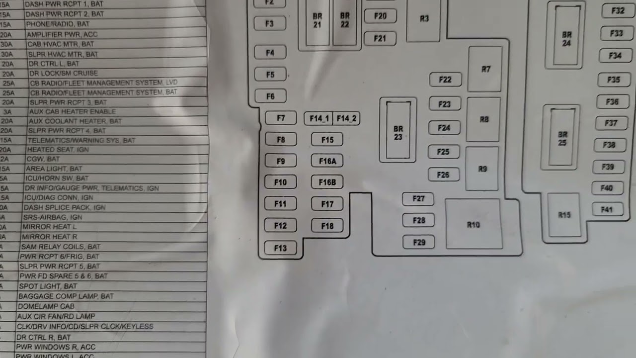
We have the 2024 Freightliner Cascadia fuse box diagram ready for you. It contains detailed information, including fuse locations, amperage ratings, and circuit descriptions. This downloadable file is an invaluable resource for anyone who wants to understand and maintain their Cascadia's electrical system.