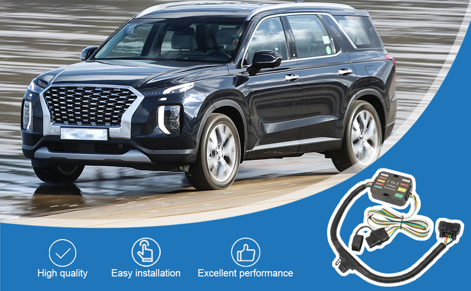
2024 Hyundai Palisade Trailer Wiring Harness
Let's dive into the 2024 Hyundai Palisade trailer wiring harness. Whether you're diagnosing electrical gremlins, planning an upgrade, or simply trying to understand your vehicle's towing capabilities, having a solid understanding of this system is crucial. This guide will walk you through the key components, functionality, and troubleshooting steps, providing you with the knowledge to confidently tackle trailer wiring issues.
Purpose of Understanding the Wiring Harness
Why bother with a wiring diagram? The trailer wiring harness is the critical interface between your Palisade and any trailer you might be towing. It's responsible for providing power to the trailer's lights (running lights, brake lights, turn signals), ensuring safe and legal operation. Understanding the harness allows you to:
- Diagnose electrical problems: Identify shorts, opens, or incorrect wiring that can cause lights to malfunction.
- Perform repairs: Replace damaged connectors, wires, or modules.
- Plan upgrades: Install additional lighting or accessories on your trailer.
- Ensure compatibility: Verify that your trailer's wiring is compatible with your Palisade's system.
- Improve safety: Correct wiring errors that could lead to accidents.
Key Specs and Main Parts
The 2024 Palisade typically uses a standard 7-way RV blade connector at the rear of the vehicle. This connector carries all the necessary signals for trailer lights and, optionally, trailer brakes and auxiliary power. Let's break down the main parts:
- 7-Way RV Blade Connector: This is the main interface point. It features seven blades, each carrying a specific signal.
- Trailer Brake Controller (if equipped): If your Palisade has the factory towing package, it likely includes a trailer brake controller. This controller regulates the voltage sent to the trailer's electric brakes, allowing for smooth and controlled stopping. Aftermarket controllers can also be installed.
- Wiring Harness: This is a bundle of wires connecting the 7-way connector to the vehicle's electrical system. It usually runs along the frame and is protected by a plastic conduit.
- Fuses and Relays: These protect the trailer wiring circuit from overloads and control the switching of power to different functions. They are typically located in the vehicle's main fuse box and a secondary fuse box near the rear of the vehicle.
- Trailer Module (if equipped): Some Palisade models incorporate a dedicated trailer module. This module isolates the trailer wiring from the vehicle's main electrical system, preventing damage and ensuring proper operation.
Key Specs to Consider:
- Voltage: The system operates on a 12V DC system.
- Amperage: Individual circuits are rated for specific amperage, typically 10A-20A for lights and potentially higher for trailer brakes. Consult your owner's manual for specific ratings.
- Wire Gauge: The thickness of the wires used in the harness. Thicker wires can carry more current without overheating. Typical gauges range from 16 AWG to 12 AWG.
Understanding Wiring Diagram Symbols
Wiring diagrams use standardized symbols to represent different components and connections. Here's a brief overview:
- Solid Lines: Represent wires. The thickness of the line can sometimes indicate the wire gauge (thicker lines for heavier gauge wires).
- Dashed Lines: May represent shielded cables or indicate a group of wires bundled together.
- Circles: Can represent lights (often with a symbol inside indicating the type of light).
- Squares and Rectangles: Represent components like relays, fuses, and modules.
- Ground Symbol: Looks like a downward-pointing rake, indicating a connection to the vehicle's chassis ground.
- Color Codes: Each wire is assigned a color code (e.g., BLK for black, RED for red, YEL for yellow, GRN for green, BLU for blue, BRN for brown, WHT for white). The diagram will list the color code for each wire, often abbreviated.
- Pin Numbers: The 7-way connector pins are numbered (1 through 7), and the diagram will indicate which wire connects to each pin.
Understanding these symbols is crucial for interpreting the wiring diagram correctly. Pay close attention to the color codes and pin numbers, as these are essential for identifying the correct wires.
How the Trailer Wiring Works
The trailer wiring harness essentially extends the vehicle's lighting and braking systems to the trailer. When you activate the turn signals, brake lights, or running lights in the Palisade, the corresponding signals are sent through the wiring harness to the trailer. If equipped with a trailer brake controller, when the brake pedal is pressed, the controller sends a variable voltage signal to the trailer's electric brakes, proportional to the amount of braking force applied. This ensures that the trailer brakes are applied smoothly and proportionally with the vehicle's brakes.
Here's a simplified overview of the signal flow:
- The driver activates a lighting or braking function (e.g., turns on the headlights, applies the brakes).
- The vehicle's computer or lighting control module detects the signal.
- The signal is sent to the trailer wiring harness, either directly or through the trailer module.
- The appropriate wires in the 7-way connector carry the signal to the trailer.
- The trailer's lights or brakes are activated.
Real-World Use and Basic Troubleshooting
Let's say your trailer's brake lights aren't working. Here's a basic troubleshooting approach:
- Check the trailer's lights first: Make sure the bulbs are good and the wiring on the trailer is intact.
- Check the 7-way connector: Inspect the connector for corrosion, bent pins, or loose wires. Clean the connector with electrical contact cleaner.
- Check the Palisade's fuses: Locate the fuse(s) for the trailer brake lights (refer to your owner's manual or the wiring diagram). Replace any blown fuses.
- Use a test light or multimeter: With the brake pedal depressed, use a test light or multimeter to check for voltage at the brake light pin on the 7-way connector. If there's no voltage, the problem lies upstream.
- Inspect the wiring harness: Look for damaged or corroded wires along the harness. Use a multimeter to check for continuity between the connector and the source.
- Check the trailer brake controller (if equipped): If you have a trailer brake controller, ensure it is properly adjusted and functioning. Many controllers have diagnostic features.
Common Problems:
- Blown Fuses: Often caused by shorts in the trailer wiring.
- Corroded Connectors: Can cause intermittent or complete loss of signal.
- Broken Wires: Can occur due to wear and tear or damage from road debris.
- Faulty Trailer Brake Controller: Can cause weak or non-existent trailer braking.
Safety Considerations
Working with automotive electrical systems can be dangerous. Here are some key safety precautions:
- Disconnect the battery: Before working on any electrical components, disconnect the negative (-) terminal of the battery to prevent shorts and electrical shock.
- Use proper tools: Use insulated tools to avoid accidental shorts.
- Wear safety glasses: Protect your eyes from flying debris and sparks.
- Be aware of airbags: Avoid working near airbags if possible. If you must work near them, disconnect the battery and wait at least 15 minutes for the airbag system to discharge.
- Never bypass fuses: Fuses are designed to protect the electrical system from overloads. Bypassing a fuse can lead to serious damage or fire.
- Trailer Brake Controllers: Never test the trailer brake controller wiring directly with a 12V source unless you are absolutely sure of the wiring. Applying direct voltage to the wrong wire can damage the controller or vehicle's electrical system. Use a multimeter to check for voltage and continuity.
Components like the trailer brake controller and the vehicle's main electrical system can be sensitive to voltage spikes and improper wiring. Always consult the wiring diagram and use caution when making connections. If you're not comfortable working with electrical systems, it's best to consult a qualified mechanic.
We have a 2024 Hyundai Palisade trailer wiring harness diagram available for download. This diagram will provide you with a detailed visual representation of the wiring layout, making it easier to diagnose and repair any issues. Contact us to get your copy and take your understanding of your Palisade's trailer wiring to the next level.