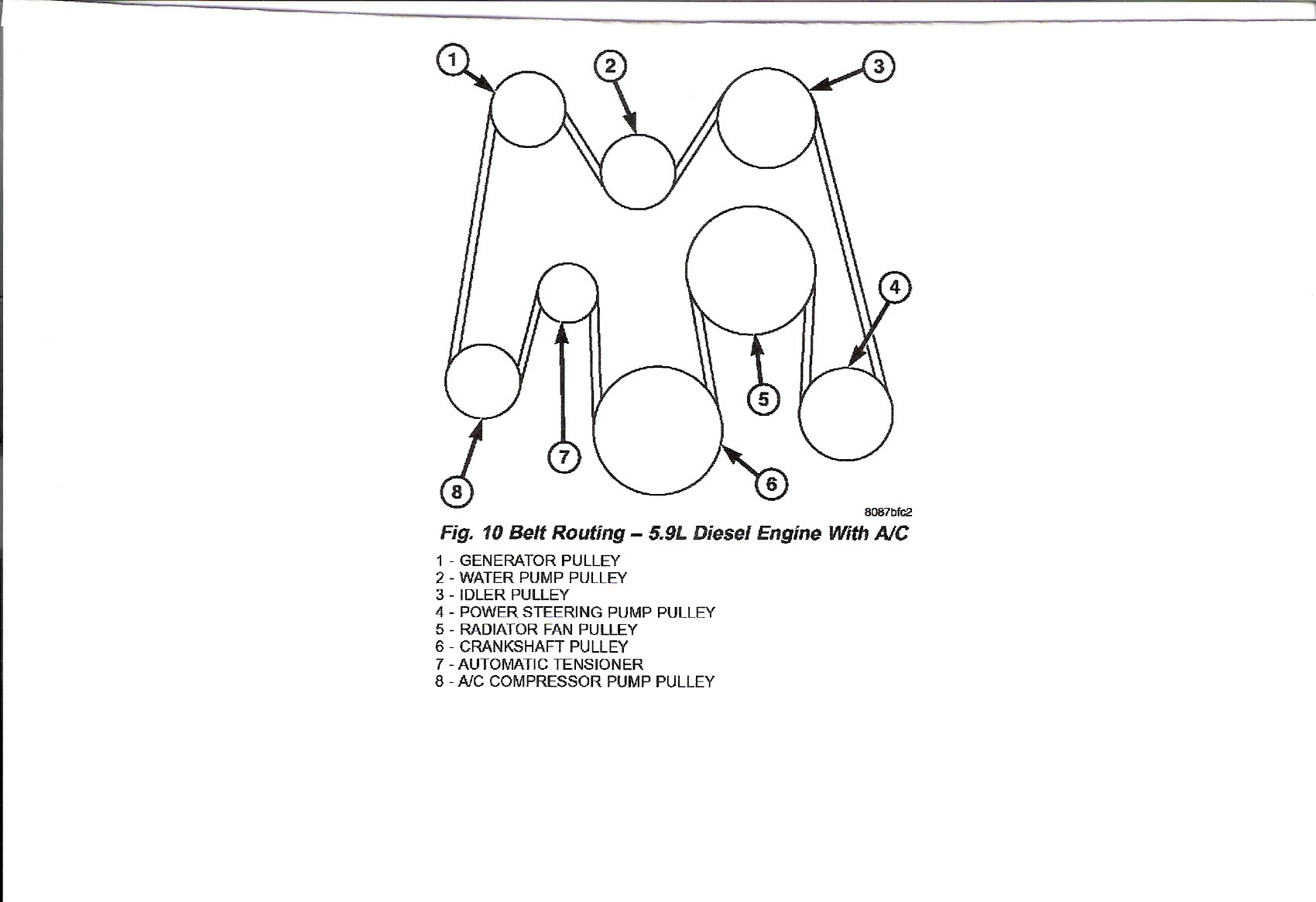
24 Valve 5.9 Cummins Serpentine Belt Diagram
The 24-valve 5.9 Cummins engine, produced from 1998.5 to 2002 (and early 2003 models in some cases), is a legendary workhorse known for its reliability and potential for modification. A critical component in keeping this engine running smoothly is the serpentine belt system. This article will provide a detailed understanding of the serpentine belt diagram for this engine, enabling you to perform maintenance, troubleshooting, and repairs with confidence.
Purpose of the Serpentine Belt Diagram
The serpentine belt diagram is an essential resource for anyone working on a 24-valve 5.9 Cummins. Its primary purpose is to illustrate the routing of the serpentine belt around the various engine accessories. Understanding this routing is crucial for several reasons:
- Belt Replacement: Knowing the correct path ensures that the new belt is installed properly, preventing slippage, noise, and premature wear.
- Accessory Troubleshooting: By understanding the belt's path, you can quickly identify which accessory is driven by the belt and diagnose potential issues. For example, if the power steering is not working, the diagram can confirm whether it's driven by the serpentine belt.
- Tensioner Identification and Function: The diagram highlights the location and type of belt tensioner, critical for maintaining proper belt tension.
- Modification and Upgrades: When adding or modifying engine accessories, the diagram helps determine if a longer or shorter belt is required.
- Preventing Catastrophic Failure: Incorrect belt routing can lead to catastrophic engine damage if the belt slips and damages other components or overheats the engine due to water pump failure.
Key Specs and Main Parts
Before diving into the diagram itself, let's review the main components of the serpentine belt system:
- Crankshaft Pulley (Damper): This pulley, located at the bottom of the engine, is driven directly by the engine's crankshaft and provides the rotational force for the entire serpentine belt system.
- Alternator Pulley: Drives the alternator, which generates electricity to power the vehicle's electrical system and charge the battery.
- Water Pump Pulley: Circulates coolant throughout the engine, preventing overheating.
- Power Steering Pump Pulley: Provides hydraulic pressure to assist with steering.
- Air Conditioning Compressor Pulley: Compresses refrigerant to provide cooling in the vehicle's cabin.
- Belt Tensioner: A spring-loaded pulley that maintains proper tension on the serpentine belt, preventing slippage and ensuring optimal performance. The tensioner on the 24v Cummins is usually an automatic spring-loaded type.
- Idler Pulley(s): Smooth pulleys that guide the belt and prevent it from rubbing against other components. Some configurations use multiple idler pulleys.
- Serpentine Belt: A single, continuous belt that drives all the engine accessories. The 5.9 Cummins typically uses a multi-ribbed, heavy-duty belt.
Belt Length: While exact belt lengths can vary slightly based on accessory configurations, a common belt length for the 24-valve 5.9 Cummins is around 93-94 inches. Always verify the correct length for your specific application.
Symbols and Diagram Interpretation
Serpentine belt diagrams typically use a standard set of symbols to represent the various components and belt routing. Common symbols include:
- Solid Lines: Represent the path of the serpentine belt.
- Arrows: Indicate the direction of belt rotation around each pulley. This is critical for ensuring the belt is routed correctly.
- Circles: Represent pulleys. Larger circles usually indicate the crankshaft pulley or accessory pulleys, while smaller circles often indicate idler pulleys.
- Shaded or Colored Areas: May be used to highlight specific components, such as the belt tensioner, or to differentiate between the "smooth" side and the "ribbed" side of the belt. The ribbed side always contacts the pulley surfaces that drive the components.
- Text Labels: Identify each pulley (e.g., "Alternator," "Water Pump," "Tensioner").
A good diagram will clearly show the routing of the belt, indicating which side of the belt (ribbed or smooth) comes into contact with each pulley. It will also clearly label the tensioner and indicate the direction of belt travel. Understanding these symbols is crucial for interpreting the diagram correctly.
How It Works
The serpentine belt system on the 24-valve 5.9 Cummins operates on a simple principle: the crankshaft pulley, driven by the engine, provides the rotational force to drive all other accessories via a single, continuous belt. The belt tensioner maintains the proper tension on the belt, ensuring that it grips the pulleys effectively and transmits the rotational force without slippage. The idler pulleys guide the belt and prevent it from interfering with other components. The specific routing of the belt is designed to maximize efficiency and minimize stress on the belt and pulleys. Proper tension is vital, as under-tensioned belts will slip, and over-tensioned belts can damage accessory bearings and the belt itself.
Real-World Use and Basic Troubleshooting
Here are some common troubleshooting scenarios where the serpentine belt diagram can be invaluable:
- Squealing or Chirping Noise: This often indicates a slipping belt. Use the diagram to inspect the belt for cracks, glazing, or wear. Also, check the tensioner for proper operation. A failing tensioner may not be maintaining adequate belt tension.
- Accessory Failure: If an accessory, such as the alternator or power steering pump, is not functioning correctly, the diagram can confirm whether it's driven by the serpentine belt. If so, inspect the belt and pulley for damage. Also, check to be sure the pulley is actually spinning when the engine is running.
- Belt Breakage: A broken belt requires immediate replacement. Before installing a new belt, use the diagram to identify the cause of the breakage. Common causes include misaligned pulleys, a seized accessory, or a worn-out tensioner. Replacing the belt without addressing the underlying issue will likely result in another failure.
- Erratic Voltage Readings: Intermittent charging issues can be related to a slipping alternator belt. The diagram will confirm proper belt routing and help diagnose tension issues.
Troubleshooting Tip: When replacing the serpentine belt, always inspect all pulleys for signs of wear, damage, or misalignment. A worn or damaged pulley can quickly destroy a new belt.
Safety Considerations
Working on the serpentine belt system can be dangerous if proper precautions are not taken. Here are some key safety considerations:
- Disconnect the Battery: Always disconnect the negative battery cable before working on the serpentine belt system to prevent accidental electrical shock.
- Engine Off and Cool: Ensure the engine is completely off and cool before working on the belt. Hot engine components can cause severe burns.
- Moving Parts: Never put your hands or tools near the serpentine belt while the engine is running. The belt can quickly pull objects into the pulleys, causing serious injury.
- Tensioner Spring: The belt tensioner is spring-loaded and can release suddenly, potentially causing injury. Use appropriate tools to relieve the tension safely.
- Eye Protection: Wear safety glasses to protect your eyes from debris.
High-Risk Components: The rotating pulleys and the spring-loaded tensioner are the most dangerous components in the serpentine belt system. Exercise extreme caution when working around these parts.
By understanding the serpentine belt diagram and following safe practices, you can confidently maintain and repair this essential engine system, ensuring the reliable operation of your 24-valve 5.9 Cummins. Remember to always consult your vehicle's service manual for specific instructions and torque specifications.
We have a detailed, high-resolution serpentine belt diagram for the 24-valve 5.9 Cummins available for download. This diagram includes detailed labels and clear routing instructions. This diagram is a valuable resource for any DIY mechanic working on this engine. Please find the download link below.
Important Note: While this article provides general information, always refer to your vehicle's specific service manual for detailed instructions and torque specifications. Incorrect procedures can damage your engine or cause injury.