3 Pin Coil Pack Wiring Diagram
Understanding the 3-pin coil pack wiring diagram is crucial for anyone delving into automotive ignition system repairs, upgrades, or performance modifications. Whether you're diagnosing a misfire, replacing a faulty coil, or simply trying to understand how your engine sparks to life, this knowledge will empower you to troubleshoot effectively and avoid costly mistakes.
Why This Diagram Matters
The ignition system is the heart of any gasoline-powered engine. A malfunctioning coil pack can lead to a multitude of problems, including:
- Misfires: An incomplete or failed combustion cycle, leading to rough running and decreased performance.
- Reduced Fuel Economy: The engine compensates for misfires by injecting more fuel.
- Damaged Catalytic Converter: Unburnt fuel entering the exhaust can damage the catalytic converter.
- Starting Problems: A weak or nonexistent spark can prevent the engine from starting.
By understanding the 3-pin coil pack wiring diagram, you can accurately diagnose issues, trace wiring faults, and ensure proper installation of new components. It's an essential skill for anyone serious about DIY automotive maintenance or modifications. You can avoid damage to your engine control unit (ECU) and ensure optimal engine performance.
Key Specs and Main Parts
Before diving into the diagram itself, let's define the key components involved:
- Coil Pack: This is the central component. It's essentially a transformer that steps up the low voltage from the battery (typically 12V) to a high voltage (tens of thousands of volts) needed to create a spark across the spark plug gap. Some coil packs are individual, while others are grouped together.
- Spark Plug: The spark plug is the endpoint of the ignition system. The high-voltage electricity jumps the gap, creating a spark that ignites the air-fuel mixture in the cylinder.
- Engine Control Unit (ECU): The "brain" of the engine. The ECU controls the timing and duration of the spark by sending signals to the coil pack. It utilizes sensors like the crankshaft position sensor (CKP) and camshaft position sensor (CMP) to determine the exact moment to trigger the spark.
- Wiring Harness: The network of wires that connects all the components together.
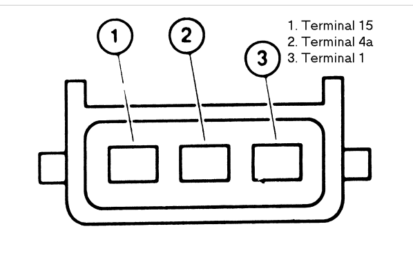
A typical 3-pin coil pack has the following connections:
- Pin 1: 12V Power Supply (often from the ignition switch or a dedicated relay).
- Pin 2: Ground.
- Pin 3: Trigger Signal from the ECU.
Symbols – Lines, Colors, and Icons
Wiring diagrams utilize standardized symbols to represent components and connections. Understanding these symbols is crucial for interpreting the diagram accurately.
- Solid Lines: Represent wires. The thickness of the line doesn't necessarily indicate wire gauge.
- Dashed Lines: Can represent shielded wires or wiring that is optional.
- Circles or Squares: Represent electrical components like resistors, capacitors, or diodes.
- Zigzag Lines: Often represent resistors.
- Ground Symbol: Typically a series of descending horizontal lines, indicating a connection to the vehicle's chassis ground.
- Color Codes: Wires are often color-coded to help identify them. Common color codes include:
- Red: Typically used for power (12V).
- Black: Typically used for ground.
- Other Colors (e.g., Green, Blue, Yellow): Used for signal wires. It's crucial to refer to the specific wiring diagram for your vehicle to confirm the color codes.
The diagram will also show how the coil pack is connected to the ECU, the ignition switch, and the vehicle's ground. It might also show fuses or relays in the circuit. Looking for these symbols and understanding their meaning is key to proper diagnosis.
How It Works
The 3-pin coil pack operates on a simple principle: it transforms low-voltage electricity into high-voltage electricity. Here's a breakdown of the process:
- Power Supply: The coil pack receives a constant 12V power supply when the ignition is on.
- ECU Trigger: The ECU monitors the engine's position using sensors like the CKP and CMP sensors. When the ECU determines that a particular cylinder needs to fire, it sends a brief ground signal to the trigger pin (Pin 3) of the coil pack.
- Coil Collapse: When the ECU provides the ground signal, it effectively completes the circuit in the coil pack's primary winding. The magnetic field builds up, then quickly collapses when the ECU stops providing the ground, or removes the ground.
- High-Voltage Generation: The rapid collapse of the magnetic field induces a very high voltage in the coil pack's secondary winding. This high voltage is then discharged through the spark plug wire to the spark plug.
- Spark Ignition: The high-voltage electricity jumps the gap at the spark plug, creating a spark that ignites the air-fuel mixture in the combustion chamber.
The timing of the ECU trigger is crucial for optimal engine performance. Incorrect timing can lead to misfires, poor fuel economy, and engine damage.
Real-World Use – Basic Troubleshooting Tips
Here are some basic troubleshooting tips using the 3-pin coil pack wiring diagram:
- No Spark: If a cylinder isn't firing, check the following:
- Power Supply: Use a multimeter to verify that the coil pack is receiving 12V when the ignition is on.
- Ground: Ensure that the coil pack has a good ground connection. Clean any corroded terminals.
- ECU Signal: Use a multimeter or oscilloscope to check for a trigger signal from the ECU when the engine is cranked. If there is no signal from the ECU, the issue could be the ECU itself, the crank or cam sensor, or the wiring in between.
- Coil Pack Test: You can test the coil pack's resistance using a multimeter, comparing the readings to the specifications in your vehicle's repair manual. A faulty coil pack will have an open circuit or a short circuit.
- Misfires: If a cylinder is misfiring, check the spark plug first. If the spark plug is good, the coil pack could be the issue. Follow the same troubleshooting steps as for "No Spark." Also, consider if the injector is working properly.
- Wiring Problems: Carefully inspect the wiring harness for any signs of damage, such as frayed wires, corroded connectors, or broken wires. Use a multimeter to check for continuity between the various points in the circuit.
Important: Always refer to the specific wiring diagram for your vehicle. Wiring configurations can vary between makes, models, and even model years.
Safety – Highlight Risky Components
Working with electrical components, especially those involving high voltage, requires extreme caution.
- High Voltage: The coil pack generates tens of thousands of volts. Never touch the spark plug wires or the coil pack while the engine is running. This can result in severe electric shock or death.
- Disconnect the Battery: Before working on any electrical components, disconnect the negative terminal of the battery to prevent accidental short circuits.
- Use Proper Tools: Use insulated tools to prevent electrical shock.
- Refer to the Repair Manual: Always refer to the specific repair manual for your vehicle for detailed instructions and safety precautions.
Remember, if you are not comfortable working with electrical components, it's best to consult a qualified mechanic.
Disclaimer: This information is for educational purposes only and should not be considered a substitute for professional advice. Automotive repair can be dangerous, and it is essential to follow proper safety procedures and consult with a qualified mechanic if you are unsure about any aspect of the repair.
We have a detailed 3-pin coil pack wiring diagram that you can download for your reference. This diagram covers many common configurations and will be a valuable tool in your troubleshooting efforts. Feel free to use it to study and better understand the specific electrical setup of your vehicle.