3 Pin Ignition Coil Wiring Diagram
Welcome, fellow gearheads! Today, we're diving deep into the fascinating world of 3-pin ignition coils and their wiring diagrams. Understanding this system is crucial for anyone looking to diagnose engine problems, perform basic maintenance, or even dabble in automotive modifications. This isn't just about replacing a part; it's about understanding how that part works and why it's wired the way it is. Think of this guide as your decoder ring for the often-mysterious world under the hood.
Purpose: Why This Diagram Matters
A 3-pin ignition coil wiring diagram is your roadmap to a functioning ignition system. It serves several critical purposes:
- Troubleshooting: When your engine misfires, stumbles, or refuses to start, the wiring diagram helps you trace the electrical path and pinpoint the faulty component – whether it’s the coil itself, a wiring issue, or a problem with the engine control unit (ECU).
- Repair and Replacement: Accurately identifying and replacing a damaged coil is essential for restoring engine performance. The diagram ensures you connect the new coil correctly, preventing further damage.
- Learning and Understanding: Gaining a deep understanding of the ignition system's operation can empower you to perform more advanced maintenance and modifications. You'll be able to diagnose issues beyond simple component swaps.
- Modification and Upgrades: If you're considering upgrading your ignition system for improved performance, the wiring diagram is invaluable for ensuring proper installation and compatibility.
Key Specs and Main Parts
Before we jump into the wiring diagram itself, let's define the key components and their specifications.
- Ignition Coil: This is the heart of the system. It's essentially a transformer that takes the relatively low voltage from the car's electrical system (typically 12V) and steps it up to the high voltage (often 20,000-40,000 volts or more) needed to create a spark across the spark plug gap. 3-pin coils are typically found in coil-near-plug or coil-on-plug (CNP/COP) systems, where each cylinder has its own dedicated coil.
- ECU (Engine Control Unit): Also known as the ECM (Engine Control Module), this is the brain of the engine. It monitors various sensors and controls the ignition timing and fuel injection. The ECU signals the ignition coil when to fire.
- Primary Winding: This is the lower-voltage side of the ignition coil. It receives the 12V power supply and the signal from the ECU.
- Secondary Winding: This is the high-voltage side of the ignition coil. It's connected to the spark plug. The ratio of turns between the primary and secondary windings determines the voltage step-up.
- Spark Plug: The final destination for the high-voltage spark. The spark ignites the air/fuel mixture in the cylinder, starting the combustion process.
- Wiring Harness: The network of wires that connect all the components together. Wires are typically color-coded to aid in identification.
A typical 3-pin ignition coil will have the following connections:
- Power (12V): A constant 12-volt supply from the car's electrical system. This is often a fused connection for safety.
- Ground: Provides a return path for the current.
- ECU Signal (Trigger): The signal from the ECU that tells the coil when to fire. This is often a pulse-width modulated (PWM) signal, where the duration of the pulse determines the dwell time (the amount of time the coil is energized before firing).
Symbols: Decoding the Wiring Diagram
Understanding the symbols used in a wiring diagram is crucial. Here's a breakdown of the common symbols you'll encounter:
- Solid Lines: Represent wires. Thicker lines often indicate wires carrying more current.
- Dashed Lines: Can represent shielded wires or connections within a component.
- Color Codes: Wires are often color-coded. Common colors include Red (power), Black (ground), and various other colors for signal wires (e.g., Blue, Green, Yellow). The color code is usually indicated next to the wire on the diagram. Knowing the color codes for your specific vehicle is essential.
- Circles/Dots: Represent wire connections (splices or junctions).
- Rectangles/Squares: Typically represent components like relays, switches, or the ECU itself.
- Ground Symbol: Usually looks like a series of downward-pointing triangles or a horizontal line with short vertical lines extending downwards.
- Coil Symbol: A coiled line, often with labels indicating the primary and secondary windings.
- Fuse Symbol: A wavy line inside a rectangle.
Important Note: Wiring diagrams can vary slightly between manufacturers and even between different models of the same manufacturer. Always consult the wiring diagram specific to your vehicle.
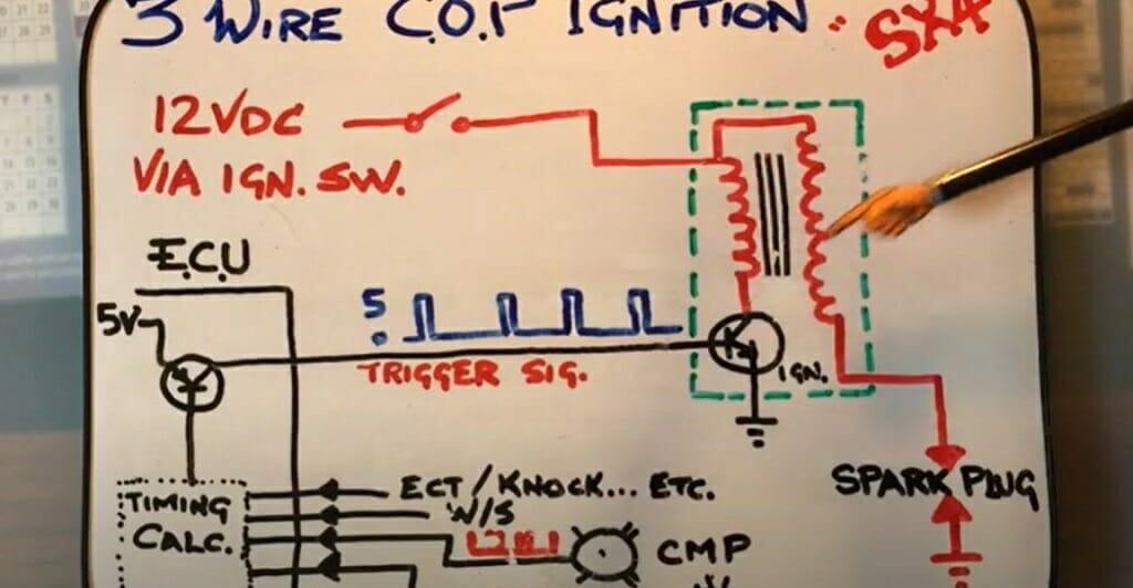
How It Works: The Ignition Sequence
Here's a simplified explanation of how the 3-pin ignition coil system works:
- Power Supply: The ignition coil receives a constant 12V power supply from the car's battery.
- ECU Signal: The ECU monitors engine speed, load, and other parameters. When the ECU determines that a particular cylinder needs to fire, it sends a signal to the ignition coil.
- Coil Charging (Dwell Time): The ECU signal activates the primary winding of the ignition coil. This causes a magnetic field to build up around the coil. The time the coil is energized (dwell time) is carefully controlled by the ECU. Insufficient dwell can lead to a weak spark, while excessive dwell can overheat the coil.
- Coil Firing: When the ECU deactivates the signal to the primary winding, the magnetic field collapses rapidly. This rapid change in the magnetic field induces a high voltage in the secondary winding.
- Spark Generation: The high voltage from the secondary winding travels to the spark plug, creating a spark across the spark plug gap. This spark ignites the air/fuel mixture in the cylinder.
Key Concept: The ECU controls the timing and duration of the ignition event, ensuring that the spark occurs at the optimal moment for efficient combustion.
Real-World Use: Basic Troubleshooting Tips
Here are some basic troubleshooting tips for diagnosing problems with a 3-pin ignition coil system:
- Check for Spark: Use a spark tester to verify that the spark plug is receiving a strong spark. If there's no spark, the problem could be the coil, the wiring, or the ECU.
- Inspect Wiring: Carefully inspect the wiring harness for any signs of damage, such as frayed wires, loose connections, or corrosion. Use a multimeter to check for continuity and voltage at the coil connector.
- Test the Coil: Use a multimeter to measure the resistance of the primary and secondary windings. Compare your readings to the specifications in the vehicle's service manual. A significant deviation from the specified resistance indicates a faulty coil.
- Check the ECU Signal: Use a multimeter or oscilloscope to check for the presence of a signal from the ECU at the coil connector. If there's no signal, the problem could be with the ECU itself or the wiring between the ECU and the coil.
- Scan for Codes: Use an OBD-II scanner to check for any diagnostic trouble codes (DTCs) related to the ignition system. These codes can provide valuable clues about the source of the problem.
- Swap Coils: If you suspect a faulty coil, you can try swapping it with a coil from a known-good cylinder. If the misfire follows the coil, then the coil is likely the problem.
Safety: Handle With Care
Working with ignition systems involves high voltages, so safety is paramount. Here are some safety precautions to keep in mind:
- Disconnect the Battery: Always disconnect the negative battery cable before working on the ignition system. This will prevent accidental shocks and damage to the electrical system.
- Avoid Touching Spark Plug Wires: Never touch spark plug wires while the engine is running. The high voltage can deliver a painful and potentially dangerous shock.
- Use Insulated Tools: Use insulated tools when working on the ignition system to protect yourself from electric shock.
- Work in a Well-Ventilated Area: When working with gasoline or other flammable materials, work in a well-ventilated area to prevent the buildup of explosive fumes.
- Be Aware of Residual Voltage: Even after the engine is turned off, there may be residual voltage in the ignition system. Use a voltmeter to discharge any residual voltage before touching any components.
Important Warning: The ignition system can generate extremely high voltages. Exercise extreme caution when working on this system. Improper handling can result in serious injury or death.
With this knowledge and a reliable wiring diagram, you're well-equipped to tackle most 3-pin ignition coil issues. Remember to always consult your vehicle's specific service manual for detailed instructions and specifications.
We have prepared a detailed 3-Pin Ignition Coil Wiring Diagram file for you. This diagram incorporates the key concepts discussed in this article, providing a practical visual aid for your diagnostic and repair endeavors.