
3 Speed 4 Wire Fan Switch Wiring Diagram
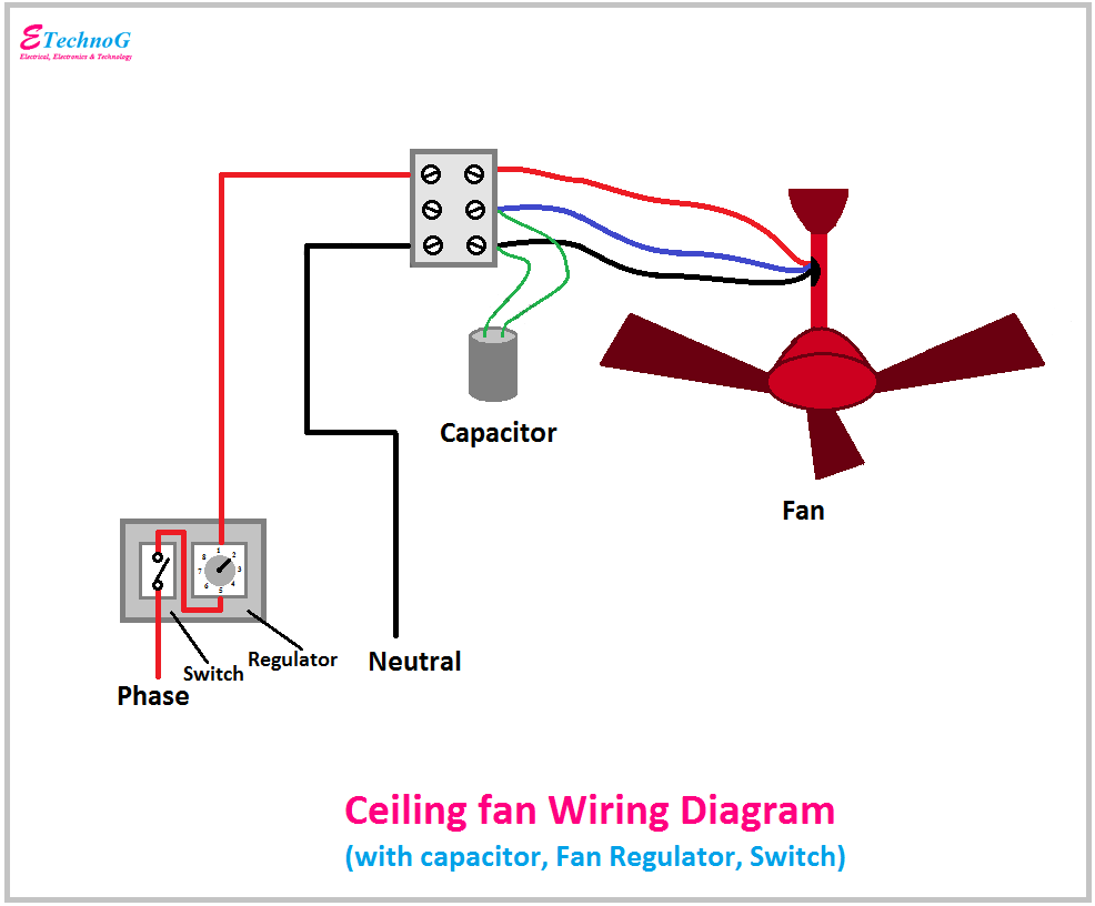
Alright, let's dive into the wiring diagram for a 3-speed, 4-wire fan switch. Whether you're troubleshooting a faulty ventilation system in your classic car, customizing a hot rod, or simply trying to understand the electrical guts of your vehicle, grasping this diagram is crucial. It’s not rocket science, but ignoring the details can lead to fried components and frustration. We'll break down the components, explain how it all works, and give you the knowledge to safely diagnose and repair these systems.
Purpose of Understanding the Diagram
Why bother with this diagram? Several reasons. First, diagnostics. If your fan only works on high, or not at all, this diagram is your roadmap to finding the problem. Second, repairs. Replacing a faulty switch or even rewiring a section of your harness becomes much simpler when you understand the current flow. Third, modification. Maybe you're adding a custom fan controller or integrating a new climate control system. Knowing how the original fan switch is wired is vital for a seamless and safe integration.
Key Specs and Main Parts
Before we get to the diagram itself, let’s identify the key components. This is a relatively simple system, but understanding the parts is essential.
- 3-Speed Fan Switch: This is the heart of the system. It’s a rotary or toggle switch with four positions: Off, Low, Medium, and High. Internally, it uses different resistive paths to control the voltage supplied to the fan motor.
- Fan Motor: The electric motor that drives the fan blades. Typically a DC motor with two wires (power and ground), but in this configuration, it interacts with the resistor network controlled by the switch.
- Resistor Block (or Resistors): This is a crucial element. It's usually a ceramic block with multiple resistors, each corresponding to a different fan speed. The resistors reduce the voltage supplied to the fan motor, resulting in lower speeds. Without them, you'd only have the High speed available.
- Wiring Harness: The bundle of wires connecting all the components. Wire gauge (thickness) is important here, as it must be sufficient to handle the current draw of the fan motor. Using too thin a wire can cause overheating and potentially a fire.
- Power Source: Usually, this is the car's 12V electrical system, often connected through a fuse or circuit breaker to protect the system from overloads.
- Ground Connection: A solid, reliable ground is essential for proper operation. This is usually connected to the vehicle's chassis.
Diagram Symbols Explained
The wiring diagram isn’t just a bunch of lines; it's a standardized language. Here’s a basic key:
- Solid Lines: Represent wires. The thickness might indicate the wire gauge (thicker lines = thicker wires).
- Dashed Lines: Often indicate a connection to ground or a shielded wire.
- Circles: Can represent connections or terminals.
- Rectangles: Typically represent components like the switch, resistor block, or fuse.
- Zigzag Lines: Usually symbolize resistors.
- Colors: Wire colors are *extremely* important for accurate wiring. Typical colors include:
- Red: Power (12V)
- Black: Ground
- Other colors (e.g., Blue, Brown, Yellow): Used for the different speed outputs.
- Switch Symbols: These vary but generally show the switch positions and the connections made in each position. A rotary switch will often show a central contact that rotates to connect to different output terminals.
Don't underestimate the importance of wire colors! Always double-check your connections against the diagram. If colors have faded or been altered, use a multimeter to trace the wires and identify their function.
How It Works: The Circuit in Action
Here’s how the 3-speed fan switch system operates:
- Power Input: The switch receives a 12V power supply from the vehicle's electrical system.
- Switch Positions: When the switch is in the "Off" position, no power flows to the fan motor.
- Low Speed: In the "Low" position, the switch connects the power supply to the fan motor *through* a large resistor. This resistor significantly reduces the voltage applied to the motor, resulting in a low fan speed.
- Medium Speed: The "Medium" position connects the power supply to the fan motor through a smaller resistor than the "Low" setting. This results in a higher voltage and a medium fan speed.
- High Speed: In the "High" position, the switch bypasses the resistors entirely, directly connecting the 12V power supply to the fan motor. This provides the maximum voltage and the highest fan speed.
- Ground: The other side of the fan motor is connected to ground, completing the circuit.
Think of it like a water hose. The resistors are like kinks in the hose. The more kinks (resistance), the less water (voltage) flows through. The High speed is like removing the kinks altogether for full flow.
Real-World Use: Troubleshooting Tips
Here are some common problems and how to use the diagram to diagnose them:
- Fan only works on High: This is a classic sign of a faulty resistor block. The resistors for the Low and Medium speeds have likely burned out. Use a multimeter to check the resistance values of each resistor. If they're open (infinite resistance), they need to be replaced.
- Fan doesn’t work at all: Check the fuse first. If the fuse is good, use a multimeter to check for voltage at the switch input. If there's no voltage, trace the power supply wire back to the source. Also, check the ground connection for the fan motor. A loose or corroded ground can prevent the fan from working.
- Fan works intermittently: This could be a loose connection at the switch, resistor block, or fan motor. Carefully inspect all connections for corrosion or damage. A little electrical contact cleaner can work wonders. You can also perform a voltage drop test along the circuit to pinpoint areas of high resistance.
- Switch is getting hot: This indicates excessive current flow, often due to a short circuit in the fan motor or a wiring problem. Immediately disconnect the power and investigate. Don't ignore this, as it's a fire hazard.
Safety: Handle with Care!
Working with automotive electrical systems can be dangerous if you’re not careful. Always disconnect the negative battery terminal before working on any electrical components. This prevents accidental shorts and potential shocks. The resistor block can get very hot during operation, so avoid touching it while the fan is running. Be mindful of sharp edges and tight spaces. Use insulated tools to minimize the risk of shorts. Fuses are there to protect the circuit. Always use the correct amperage fuse rating, as specified in your vehicle’s manual. Using a higher amperage fuse can bypass the protection and cause a fire.
Important Note: Always consult your vehicle's specific wiring diagram. While this article provides a general overview, the wiring colors and component locations may vary.
Remember, electricity doesn't discriminate. Take your time, double-check your work, and prioritize safety.
We have a downloadable PDF file of a typical 3-speed 4-wire fan switch wiring diagram. It's a valuable reference tool that you can print out and keep in your garage. You can find the download link at the end of this article [Hypothetical download link placement].