3 Switch Light Switch Wiring Diagram
Okay, let's dive into the world of three-way light switch wiring. This isn't quite as simple as your typical single-pole switch, but with a clear understanding of the wiring diagram, you'll be able to troubleshoot existing setups, install new ones, or even just impress your friends with your electrical prowess. We'll break down the purpose, key components, diagram symbols, operation, real-world applications, and most importantly, the crucial safety precautions involved. Consider this your comprehensive guide to understanding and utilizing a three-way light switch wiring diagram.
Purpose of a Three-Way Light Switch Wiring Diagram
Why bother understanding this diagram? Well, a three-way switch setup allows you to control a single light fixture from two different locations. Think hallways, stairwells, or large rooms with multiple entrances. The wiring diagram is your roadmap to understanding how these switches interact to achieve this seemingly magical feat. More specifically, it's crucial for:
- Troubleshooting: When a light isn't behaving as expected, the diagram helps you trace the wiring and identify the faulty component (switch, wire, or fixture).
- Installation: Whether you're adding a new light or replacing old switches, the diagram guides you through the correct wiring configuration.
- Modification: If you're adding smart switches or other advanced features, understanding the existing wiring is essential to avoid conflicts.
- Learning: Even if you don't plan on doing any electrical work yourself, understanding the diagram provides valuable insight into how electrical systems function.
Key Specs and Main Parts
Before we delve into the diagram itself, let's identify the key components involved in a three-way switch setup:
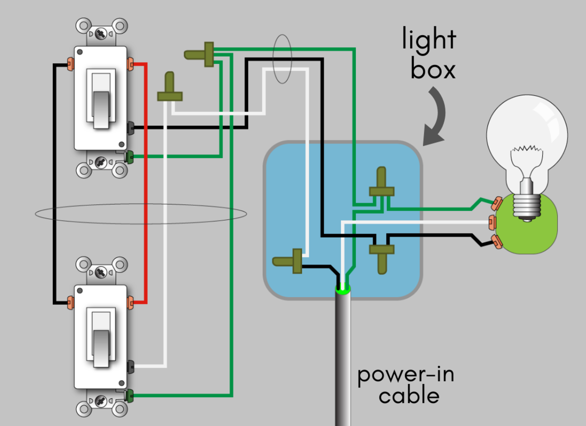
- Three-Way Switches: These aren't your standard on/off switches. They have three terminals (screws) instead of two. Two of these terminals are called travelers, and one is a common terminal.
- Power Source: This is your electrical panel where the circuit breaker resides. It provides the hot (live) wire.
- Light Fixture: The lamp or fixture that you're controlling.
- Neutral Wire: The return path for the electricity to the panel. Usually white.
- Ground Wire: A safety wire, typically bare copper or green, connected to ground.
- Traveler Wires: The pair of wires that connect the two three-way switches. These are the key to the three-way functionality.
- Wire Connectors (Wire Nuts): Used to safely join wires together.
- Electrical Boxes: Housings for the switches and wiring connections. These provide protection and prevent loose wires from causing hazards.
Understanding the Symbols in the Diagram
The wiring diagram uses a symbolic language to represent the electrical components and connections. Here's a breakdown of the common symbols:
- Lines: Represent wires. A solid line indicates a continuous wire.
- Color Coding:
- Black: Typically represents the hot (live) wire carrying electricity from the power source.
- White: Represents the neutral wire, the return path to the power source.
- Green (or Bare Copper): Represents the ground wire, a safety wire.
- Red: Often used for traveler wires in three-way switch circuits.
- Switches: Three-way switches are often represented by a symbol with three connection points. The symbol visually depicts the switch's ability to toggle the connection between the common terminal and either of the traveler terminals.
- Light Fixture: Usually represented by a circle with an 'X' or a stylized lamp symbol.
- Junction Box: Often represented by a circle or rectangle. This is where multiple wires are connected.
How a Three-Way Switch Works
The secret to a three-way switch is in the traveler wires. Here's the basic principle:
- Power Source: The hot wire from the electrical panel is connected to the common terminal of one of the three-way switches.
- Traveler Wires: The two traveler terminals on the first switch are connected to the two traveler terminals on the second switch.
- Second Switch to Light: The common terminal on the second switch is connected to the light fixture.
- Neutral and Ground: The neutral wire runs directly from the power source to the light fixture. The ground wires are connected to the switches, the fixture, and the electrical box.
When you flip either switch, it changes the connection between its common terminal and one of the traveler terminals. This action either completes or breaks the circuit, turning the light on or off, respectively. Because both switches can independently change this connection, you can turn the light on from one location and off from the other, or vice-versa.
To put it another way, imagine the traveler wires as two different paths for the electricity to flow. Flipping a switch simply chooses which path is active. If neither path allows a complete circuit to the light, it's off. If either path allows a complete circuit, it's on.
Real-World Use and Basic Troubleshooting
Okay, your light's misbehaving. Here are a few troubleshooting tips based on the wiring diagram:
- Light Doesn't Turn On From Either Switch:
- Check the circuit breaker. Is it tripped?
- Use a multimeter to verify that the hot wire is supplying power to the first switch.
- Check that the light bulb itself is functional.
- Inspect all wire connections for looseness or corrosion.
- Light Turns On From One Switch But Not the Other:
- Inspect the switch that doesn't turn the light on. Is it damaged?
- Carefully check the traveler wire connections at both switches. A loose connection here can cause problems.
- Light Stays On Constantly:
- This is rare, but could indicate a short circuit. Immediately turn off the breaker and investigate.
Safety First! Highlighting Risky Components
Electricity is dangerous. Never work on electrical circuits without taking the following precautions:
- Turn Off the Power: Before you even touch a wire, turn off the circuit breaker that controls the circuit you're working on. Verify that the power is off with a non-contact voltage tester.
- Wear Safety Glasses: Protect your eyes from sparks or debris.
- Use Insulated Tools: Use tools with insulated handles to prevent shocks.
- Work in Dry Conditions: Never work on electrical circuits in wet or damp environments.
- Do Not Overcrowd Boxes: Ensure wiring is neatly arranged and does not overfill the electrical boxes, which could cause overheating.
The most dangerous components are obviously the hot wires. Always treat any wire as if it were live until you've verified that the power is off. Incorrect wiring can lead to short circuits, fire hazards, and even electrocution. If you're not comfortable working with electricity, hire a qualified electrician.
Understanding the three-way light switch wiring diagram empowers you to diagnose issues and perform installations safely and effectively. Remember to always prioritize safety and double-check your work. This knowledge allows you to maintain, repair, and improve your electrical systems with confidence.
By the way, we have a downloadable version of a standard three-way light switch wiring diagram available for your convenience. Just reach out, and we'll send you the file.