
3 Wire Alternator Wiring Diagram Chevy
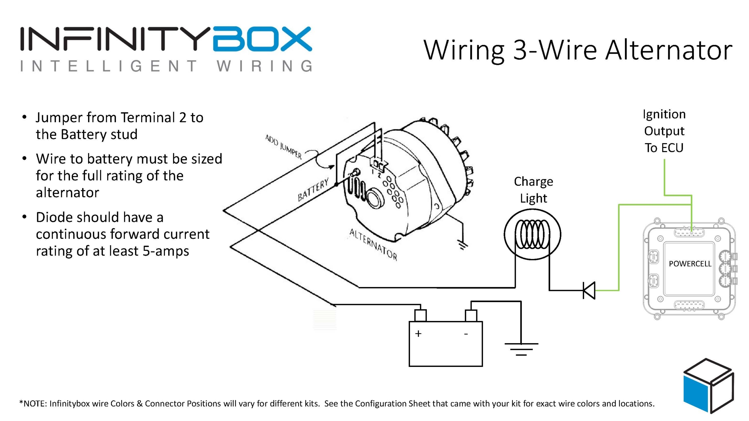
Alright, let's dive into the 3-wire alternator wiring diagram for a Chevy. Understanding this diagram is crucial whether you're troubleshooting charging issues, swapping in a new alternator, performing an engine swap, or just expanding your automotive knowledge. This guide is designed for the intermediate DIYer – we'll cover the technical details without getting lost in jargon, but we'll also provide clear explanations.
Purpose: Why Bother?
Why learn about this diagram? Several good reasons exist:
- Troubleshooting Charging Problems: If your battery isn't staying charged, the alternator is often the culprit. This diagram allows you to systematically check the wiring and connections.
- Alternator Replacement: When replacing an alternator, ensuring correct wiring is paramount to avoid damage.
- Engine Swaps/Modifications: Installing a different engine, particularly one that isn't a direct replacement, frequently requires adapting the alternator wiring.
- Understanding Electrical Systems: Grasping the alternator circuit is fundamental to understanding broader automotive electrical systems.
- Upgrading Electrical Systems: If you're adding high-draw accessories, understanding your charging system's capabilities and limitations (and its wiring) is critical.
Key Specs and Main Parts
Before we jump into the diagram, let's review the key components and some typical specifications. Keep in mind that exact values can vary depending on the year, make, and model of your Chevy.
Main Components:
- Alternator: The heart of the charging system. It converts mechanical energy from the engine into electrical energy to charge the battery and power the electrical system.
- Battery: Provides the initial electrical energy to start the engine and acts as a reservoir for the electrical system. Typically 12V.
- Voltage Regulator: A critical component, often integrated within the alternator on modern systems. The regulator controls the alternator's output voltage to prevent overcharging and damage to the battery and electrical components. Older systems may have an external voltage regulator.
- Battery Cables: Heavy-gauge cables providing the high-current connection between the battery and the vehicle's electrical system.
- Wiring Harness: A bundle of wires that carries electrical signals and power throughout the vehicle.
- Fuses/Fusible Links: Safety devices that protect the electrical system from overcurrent.
Typical Specifications:
- Output Voltage: Typically around 13.8-14.7 volts when the engine is running.
- Output Current (Amperage): Varies greatly. Stock alternators can range from 60 amps to well over 100 amps depending on the vehicle's electrical load. Aftermarket high-output alternators can exceed 200 amps.
- Wire Gauge: The wire gauge (thickness) is crucial for handling the current. The main charging wire (from the alternator output to the battery) is usually a heavy gauge, such as 8 AWG or even 4 AWG for high-output systems. Smaller wires are used for the regulator and sensing circuits.
Decoding the Diagram: Symbols, Lines, and Colors
Understanding the diagram symbols is essential. While specific styles can vary slightly, the core principles remain consistent.
- Solid Lines: Represent wires. Thicker lines generally indicate wires carrying higher current.
- Dashed Lines: May indicate grounds or connections to the chassis.
- Color Coding: Automotive wiring uses standard color codes, although these can vary slightly. Common colors include:
- Red: Often used for positive (+) battery connections and power wires.
- Black: Typically used for ground (-) connections.
- Orange/Yellow: Often used for switched power (power only when the ignition is on).
- Blue/Green: Can be used for various signals. Refer to the specific diagram for their purpose.
- Symbols:
- Alternator: A stylized representation of the alternator, often with a circle or square containing a symbol resembling a generator.
- Battery: Represented by alternating long and short parallel lines, with a '+' sign indicating the positive terminal and a '-' sign indicating the negative terminal.
- Fuse: A zig-zag line within a rectangle or circle.
- Ground: A series of downward-pointing triangles, indicating a connection to the chassis.
- Voltage Regulator: Usually represented as a rectangle with input and output terminals. If it is internal, it will be shown "inside" the alternator symbol.
In a typical 3-wire alternator setup on a Chevy, you'll find the following three connections:
- Battery (BAT or B+): A heavy-gauge wire directly connecting the alternator's output terminal to the positive (+) terminal of the battery. This is the main charging wire.
- Sense Wire (Voltage Sense or Remote Sense): This wire senses the voltage at a remote location, usually at the battery or a distribution point in the electrical system. The voltage regulator uses this reading to compensate for voltage drop across the wiring and ensure the battery receives the correct charging voltage. This connection is sometimes labeled "S."
- Exciter Wire (Ignition or Field): This wire provides a small amount of current to initially "excite" the alternator's field windings when the ignition is turned on. This current is needed to start the alternator generating power. This connection is often labeled "I" or "IGN." It's typically connected to a switched 12V source (i.e., a circuit that's only powered when the ignition key is in the "on" position).
How It Works: The Charging Process
Here's a simplified breakdown of how the 3-wire alternator system works:
- When the ignition is turned on, the exciter wire provides a small current to the alternator's field windings.
- The spinning rotor inside the alternator, driven by the engine's belt, creates a magnetic field due to the energized field windings.
- This rotating magnetic field induces a voltage in the stator windings.
- The alternator's internal rectifier converts the AC voltage generated in the stator windings to DC voltage.
- The voltage regulator monitors the output voltage of the alternator and adjusts the current flowing through the field windings to maintain a constant voltage (typically around 14 volts). This ensures the battery is properly charged without being overcharged. The sense wire allows the regulator to "see" the voltage at the battery, compensating for voltage drop in the wiring.
- The DC voltage from the alternator is then sent to the battery via the heavy-gauge charging wire, replenishing the battery's charge and powering the vehicle's electrical system.
Real-World Use: Basic Troubleshooting Tips
If you suspect a problem with your alternator, here are a few basic troubleshooting steps you can take (always disconnect the negative battery cable before working on the electrical system):
- Visual Inspection: Check all wiring connections for corrosion, loose connections, or damaged wires. Pay particular attention to the connections at the alternator and the battery.
- Voltage Test: With the engine running, measure the voltage at the battery terminals. A healthy charging system should produce around 13.8-14.7 volts. If the voltage is significantly lower (e.g., 12 volts or less), the alternator may not be charging correctly.
- Exciter Wire Test: With the ignition on but the engine off, use a multimeter to check for voltage at the exciter wire connector on the alternator. You should see approximately battery voltage. If there's no voltage, check the fuse for the ignition circuit.
- Sense Wire Test: With the engine running and a load applied (headlights on), compare the voltage at the alternator output terminal (B+) to the voltage at the sense wire connection. The voltage should be very close (within a few tenths of a volt). A significant difference suggests a problem with the sense wire circuit.
- Check the Ground: A bad ground connection can cause all sorts of problems. Ensure the alternator is properly grounded to the engine block or chassis.
Important: If you're not comfortable with electrical testing, it's always best to consult a qualified mechanic.
Safety: Proceed with Caution!
Working with automotive electrical systems can be dangerous. Here are some key safety precautions:
- Disconnect the Negative Battery Cable: Always disconnect the negative (-) battery cable before working on the electrical system to prevent short circuits and potential electric shock.
- Avoid Short Circuits: Be careful not to create short circuits by accidentally touching wires to ground or to each other.
- Wear Eye Protection: Wear safety glasses to protect your eyes from sparks or debris.
- Work in a Well-Ventilated Area: Batteries can produce explosive gases, so work in a well-ventilated area.
- Know Your Limits: If you're not comfortable with electrical testing or repairs, consult a qualified mechanic. The high amperage potential, especially on the B+ terminal, can cause burns or arc flashes.
We have a downloadable PDF of a typical 3-wire alternator wiring diagram for a Chevy available. This diagram can be a valuable reference tool when working on your vehicle. Understanding the diagram and the principles behind the charging system will empower you to troubleshoot and repair electrical issues with confidence. Remember to always prioritize safety and consult a professional if you're unsure about any aspect of the repair.