3 Wire Camshaft Position Sensor Wiring Harness
Understanding the 3-wire Camshaft Position (CMP) sensor wiring harness is crucial for anyone involved in automotive diagnostics, repairs, or modifications. Whether you're troubleshooting a mysterious engine code, replacing a faulty sensor, or simply expanding your automotive knowledge, grasping the intricacies of this system can save you time, money, and frustration. This article will delve into the specifics of the 3-wire CMP sensor wiring harness, equipping you with the knowledge to confidently tackle related tasks.
Purpose of Understanding the Diagram
Why bother learning about this diagram? Because it's your roadmap to understanding the CMP sensor circuit. This knowledge is invaluable for several reasons:
- Troubleshooting Engine Problems: A malfunctioning CMP sensor can cause a variety of engine issues, from rough idling and poor performance to a complete no-start condition. Understanding the wiring allows you to pinpoint the source of the problem, whether it's a faulty sensor, a broken wire, or a problem with the PCM (Powertrain Control Module).
- Performing Repairs: When replacing a damaged CMP sensor or repairing damaged wiring, knowing the exact connections is essential to ensure proper operation. Incorrect wiring can damage the sensor, the PCM, or both.
- Modifications and Swaps: If you're working on engine swaps or modifying your vehicle, understanding the CMP sensor wiring is crucial for integrating the new engine or components correctly.
- Preventative Maintenance: Regularly inspecting the wiring harness for damage or corrosion can help prevent future problems.
Key Specs and Main Parts
The 3-wire CMP sensor system generally consists of these key components:
- Camshaft Position Sensor (CMP): This sensor detects the position of the camshaft. It's typically a Hall-effect sensor or a variable reluctance sensor. The 3-wire configuration usually indicates a Hall-effect sensor, which requires a power supply, ground, and a signal wire.
- Wiring Harness: This is the network of wires that connects the CMP sensor to the PCM and other components. It's designed to protect the wires from damage and environmental factors.
- Powertrain Control Module (PCM): The PCM is the vehicle's main computer. It receives the signal from the CMP sensor and uses this information to control ignition timing, fuel injection, and other engine functions.
- Connectors: These are the plugs that connect the CMP sensor to the wiring harness and the wiring harness to the PCM. They provide a secure and reliable electrical connection.
Hall-Effect Sensor vs. Variable Reluctance Sensor: While both types of CMP sensors detect camshaft position, they operate differently. A Hall-effect sensor requires an external power source (hence the 3 wires) and generates a digital signal. A variable reluctance sensor generates its own voltage signal based on the changing magnetic field as the camshaft rotates, and often uses only two wires. Understanding which type you have is important for accurate diagnosis.
Symbols and Wire Colors
Reading the wiring diagram effectively relies on understanding its symbols and conventions. Here's a breakdown of common elements:
- Lines: Solid lines represent wires. Dashed lines may represent shielded wires or grounds.
- Wire Colors: Each wire is typically identified by a color code. Common colors include Red (power), Black (ground), and various other colors for signal wires. Refer to your vehicle's specific wiring diagram for the correct color codes. Never assume wire colors are universal across different makes and models.
- Connectors: Represented by squares or rectangles with numbers or letters indicating the pin assignments.
- Ground Symbols: Usually a series of horizontal lines decreasing in size, or a triangle pointing downwards.
- PCM Representation: The PCM is often represented as a large rectangle with labeled pins.
- Sensor Symbol: Typically a simplified representation of the sensor itself, often with labeled terminals (+, -, SIG).
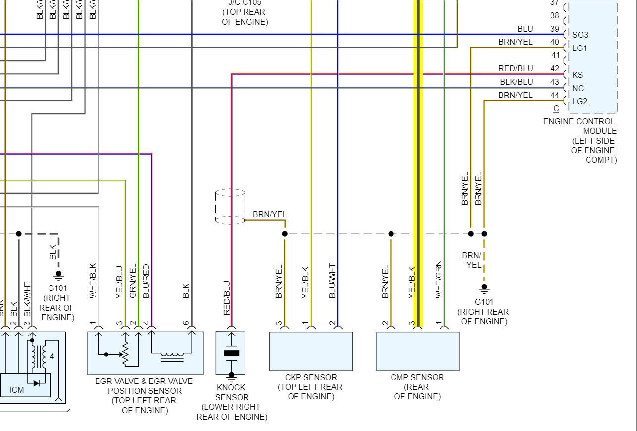
The wiring diagram will show the path of each wire from the CMP sensor to the PCM, including any connectors or splices along the way. It's crucial to pay attention to the wire colors and pin numbers to ensure accurate identification.
How It Works
The 3-wire CMP sensor system works by providing the PCM with information about the camshaft's position. Here's a step-by-step explanation:
- Power Supply: The PCM provides a regulated voltage (typically 5 volts or 12 volts) to the CMP sensor through one of the wires (usually Red).
- Ground: The CMP sensor is grounded to the vehicle's chassis or the PCM through another wire (usually Black). This provides a return path for the electrical current.
- Signal Generation: As the camshaft rotates, a target wheel (reluctor ring) on the camshaft passes by the CMP sensor. In the case of a Hall-effect sensor, this interrupts a magnetic field, causing the sensor to generate a digital signal.
- Signal Transmission: The signal from the CMP sensor is sent to the PCM through the third wire (the signal wire).
- Signal Processing: The PCM uses the CMP sensor signal to determine the camshaft's position. This information is then used to control ignition timing, fuel injection, and other engine functions.
The PCM compares the signal from the CMP sensor with the signal from the Crankshaft Position (CKP) sensor to accurately determine engine position and timing. If the CMP signal is missing or erratic, the PCM may trigger a diagnostic trouble code (DTC) and potentially enter a "limp mode" to protect the engine.
Real-World Use: Basic Troubleshooting Tips
Here are some basic troubleshooting tips you can use with the wiring diagram:
- Check for Diagnostic Trouble Codes (DTCs): Use an OBD-II scanner to check for any DTCs related to the CMP sensor. Common codes include P0340 (CMP Sensor Circuit Malfunction), P0341 (CMP Sensor Circuit Range/Performance), and P0342 (CMP Sensor Circuit Low Input).
- Visual Inspection: Inspect the wiring harness and connectors for any signs of damage, corrosion, or loose connections. Pay close attention to the wiring near the sensor, as this area is often exposed to heat and vibration.
- Voltage Test: Use a multimeter to check the voltage at the CMP sensor connector with the ignition key on. You should see the specified voltage (typically 5V or 12V) on the power wire and a good ground connection.
- Signal Test: Use a multimeter or oscilloscope to check the signal from the CMP sensor while the engine is running. The signal should be a square wave or a similar pattern that corresponds to the camshaft's rotation.
- Continuity Test: Use a multimeter to check the continuity of the wires between the CMP sensor and the PCM. This will help you identify any broken or shorted wires.
Important Note: Always refer to your vehicle's specific service manual or wiring diagram for the correct voltage values, signal patterns, and pin assignments. Generic troubleshooting procedures may not be accurate for all vehicles.
Safety
Working with automotive electrical systems can be dangerous. Here are some important safety precautions to keep in mind:
- Disconnect the Battery: Before working on any electrical components, always disconnect the negative battery cable to prevent accidental shocks or shorts.
- Work in a Well-Ventilated Area: When working with fuels or solvents, always work in a well-ventilated area to avoid inhaling harmful fumes.
- Use Proper Tools: Use insulated tools and test equipment that are designed for automotive electrical systems.
- Avoid Touching Exposed Wires: Never touch exposed wires or terminals while the ignition is on or the engine is running.
- Be Careful Around the Ignition System: The ignition system contains high-voltage components that can deliver a dangerous shock. Avoid touching any ignition components while the engine is running.
High-Risk Components: The PCM and the ignition system are particularly sensitive and potentially dangerous components. Exercise extreme caution when working near these components.
By understanding the 3-wire CMP sensor wiring harness and following proper safety precautions, you can confidently troubleshoot and repair CMP sensor-related problems on your vehicle. Remember to always consult your vehicle's specific wiring diagram for accurate information and to prioritize safety when working on automotive electrical systems.
We have a detailed diagram of a typical 3-wire CMP sensor wiring harness available for download. This diagram provides a visual representation of the circuit, including wire colors, pin assignments, and connector locations. Contact us, and we will happily provide you with the file.