3 Wire Crank Position Sensor Wiring Diagram
Alright, let's talk Crank Position Sensors (CKP). Understanding the wiring of a 3-wire CKP sensor is crucial for anyone tackling engine diagnostics, performance modifications, or even just wanting to deepen their understanding of how modern engine management systems operate. This article will break down a typical 3-wire CKP sensor wiring diagram, explain its components, and equip you with the knowledge to troubleshoot common issues. Having a good grasp of this will save you time, money, and potential headaches down the road.
Why This Diagram Matters
The Crank Position Sensor is a *critical* component of your car's engine management system. Without it, the Engine Control Unit (ECU), sometimes also referred to as the Powertrain Control Module (PCM), wouldn't know the exact position and rotational speed of the crankshaft. This information is absolutely necessary for precisely timing fuel injection and ignition. A faulty or miswired CKP sensor can lead to a no-start condition, poor performance, misfires, and even engine damage.
Understanding the wiring diagram is essential for:
- Repairing damaged wiring: Accidents happen. Wires can break, become corroded, or be damaged by rodents.
- Diagnosing sensor failures: Before replacing a CKP sensor, you need to verify the wiring and power supply are correct.
- Performing engine swaps or modifications: When swapping engines, knowing the wiring is paramount for proper integration with the existing vehicle harness.
- Learning about engine management systems: Understanding the CKP sensor is a fundamental step in understanding how your engine works.
Key Specs and Main Parts
A typical 3-wire Crank Position Sensor setup consists of the following:
- The CKP Sensor: This is the actual sensor itself, usually mounted near the crankshaft pulley or flywheel. It senses the passing of teeth or a specific feature (like a missing tooth) on a reluctor wheel or tone ring attached to the crankshaft.
- Reluctor Wheel/Tone Ring: This is a toothed wheel or ring attached to the crankshaft. As it rotates, the teeth pass by the sensor, generating a signal. The design of this wheel is crucial for accurate engine timing.
- Wiring Harness: The wires connecting the sensor to the ECU. These are typically insulated and protected within a larger wiring loom.
- ECU (Engine Control Unit): The brain of the engine management system. It receives the CKP sensor signal and uses it to control fuel injection, ignition timing, and other engine parameters.
Key Specs to Consider:
- Sensor Type: Typically either a Hall-effect sensor or a variable reluctance sensor. Understanding which type your vehicle uses is crucial for proper diagnosis.
- Voltage: Most CKP sensors operate on a 5V reference voltage, but some may use 12V. Always check your vehicle's specifications.
- Resistance: For variable reluctance sensors, knowing the expected resistance of the sensor coil can help diagnose internal failures.
Symbols and Wiring Diagram Explained
Let's break down the typical symbols and what they represent on a 3-wire CKP sensor wiring diagram.
Here's a general representation of the wiring:
  [Power Supply (e.g., +5V)] ---- [Wire (typically Red or Yellow)] ---- [CKP Sensor]
                                                                |
  [Ground (Chassis Ground)] -------- [Wire (typically Black or Brown)] ---|
                                                                |
  [Signal Wire] -------------------- [Wire (Color varies, e.g., Green, Blue)] -> [ECU Input]
- Solid Lines: Represent wires. Thicker lines may indicate heavier gauge wires.
- Dashed Lines: Sometimes used to indicate shielded wires or wires that are part of a harness.
- Color Codes: Wire colors are usually indicated next to the lines (e.g., RD for Red, BLK for Black, GRN for Green). Color coding is essential for correct identification!
- Ground Symbol (⏚ or similar): Indicates a connection to chassis ground. This is a common reference point for the electrical system.
- Connector Symbols: Diagrams will show the connector connecting the sensor to the harness. These symbols are often generic but indicate the physical connection point.
- Sensor Symbol: The sensor itself will be represented by a symbol specific to its type (Hall-effect or Variable Reluctance). These symbols can vary depending on the diagram.
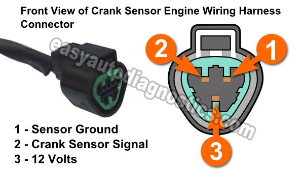
Typical Wire Functions:
- Power Supply: Provides a stable voltage (usually 5V or 12V) to the sensor.
- Ground: Provides a return path for the current and establishes a common reference point.
- Signal Wire: Carries the signal generated by the sensor back to the ECU. This signal represents the crankshaft's position.
How It Works
The CKP sensor works by detecting the passing of teeth or a feature on the reluctor wheel. The type of sensor determines how this detection happens:
- Variable Reluctance Sensor: This type of sensor contains a coil of wire wrapped around a magnet. As a tooth on the reluctor wheel passes by the sensor, it changes the magnetic field. This change in the magnetic field induces a voltage in the coil. The ECU interprets the frequency and amplitude of this voltage signal to determine the crankshaft's position and speed. These sensors generate their own voltage signal, so they don't necessarily require a direct power source. However, many have 3 wires with a signal, ground and a shield wire connected to ground.
- Hall-Effect Sensor: This type of sensor uses a semiconductor material that produces a voltage when exposed to a magnetic field. A small magnet is built into the sensor. As a tooth passes by, it disrupts the magnetic field, causing the Hall-effect sensor to generate a voltage pulse. The ECU reads these pulses to determine crank position. Hall-effect sensors require a constant power supply (usually 5V) to operate.
The ECU then uses this information to precisely time the firing of the spark plugs and the injection of fuel into the cylinders. This synchronization is critical for efficient combustion and optimal engine performance. Incorrect timing due to a faulty CKP sensor can lead to serious engine problems.
Real-World Use: Basic Troubleshooting Tips
Here are some basic troubleshooting tips you can use with your CKP wiring diagram:
- Check for Voltage at the Power Wire: Use a multimeter to verify that the correct voltage (usually 5V or 12V) is present at the power wire of the sensor with the ignition ON.
- Check for Continuity to Ground: Verify that the ground wire has a good connection to chassis ground. A poor ground connection can cause all sorts of issues.
- Check the Signal Wire: Using a multimeter or oscilloscope, check the signal wire while the engine is cranking or running. You should see a fluctuating voltage signal that corresponds to the engine's RPM. If you are using a multimeter, select AC voltage. A Hall-effect sensor will give a digital square wave and a Variable Reluctance Sensor gives an AC Sine wave.
- Inspect Wiring for Damage: Look for frayed wires, corrosion, or loose connections. Pay close attention to the connector at the sensor and the connector at the ECU.
- Check for Short Circuits: Use a multimeter to check for shorts between the wires. A short circuit can damage the sensor or the ECU.
- Scan for Diagnostic Trouble Codes (DTCs): Use an OBD-II scanner to check for codes related to the CKP sensor. These codes can provide valuable clues about the nature of the problem. Common codes include P0335 (Crankshaft Position Sensor A Circuit Malfunction), P0336 (Crankshaft Position Sensor A Circuit Range/Performance), and P0337 (Crankshaft Position Sensor A Circuit Low Input).
Example Troubleshooting Scenario:
Let's say your car won't start, and you suspect the CKP sensor. You pull up the wiring diagram and:
- Use a multimeter to check for 5V at the power wire of the CKP sensor connector. You find no voltage. This suggests a problem with the power supply circuit, possibly a blown fuse or a broken wire.
- You check the ground wire and find high resistance. You clean the ground connection point and retest. The resistance is now low. You try to start the car, and it starts right up!
Safety Considerations
Working with automotive electrical systems can be dangerous. Here are some safety precautions:
- Disconnect the Battery: Before working on any electrical component, disconnect the negative terminal of the battery. This will prevent accidental shorts and electrical shocks.
- Be Careful Around the Crankshaft Pulley: The crankshaft pulley is a rotating component that can cause serious injury. Keep your hands and tools clear of the pulley when the engine is running or cranking.
- Do Not Probe Wires with the Engine Running: Probing wires while the engine is running can damage the wiring or the ECU. Use a backprobe to test the wiring instead. This will prevent damage to the insulation on the wires.
- Use Proper Tools: Use a multimeter, oscilloscope, and other diagnostic tools that are designed for automotive use.
- Work in a Well-Ventilated Area: When working on your car, work in a well-ventilated area to avoid inhaling harmful fumes.
- Refer to the Vehicle's Service Manual: Always consult the vehicle's service manual for specific wiring diagrams and troubleshooting procedures.
Specifically, the ECU (Engine Control Unit) is a very sensitive device. Incorrect wiring or voltage spikes can easily damage it, resulting in costly repairs or replacement.
Understanding the 3-wire CKP sensor wiring diagram is a valuable skill for any DIY mechanic or car enthusiast. By understanding the components, symbols, and troubleshooting techniques outlined in this article, you'll be well-equipped to diagnose and repair CKP sensor-related issues. Remember safety first, and always refer to your vehicle's service manual for specific information.
We have a downloadable PDF file of a common 3-wire CKP sensor wiring diagram to help you further. Please contact us to access the file.