3 Wire Ford Alternator Regulator Wiring Diagram
The 3-wire Ford alternator is a popular choice for a reason: it's robust, reliable, and relatively simple to wire. Understanding its wiring diagram is crucial for anyone tackling charging system repairs, performing custom modifications, or simply wanting a deeper understanding of their vehicle's electrical system. This guide will break down the 3-wire Ford alternator regulator wiring diagram, providing the knowledge you need to troubleshoot problems, perform upgrades, and ensure your charging system operates flawlessly.
Purpose of Understanding the 3-Wire Ford Alternator Wiring Diagram
Why bother learning this? Several reasons stand out:
- Troubleshooting Charging Issues: A faulty alternator can cause dimming lights, a dead battery, and ultimately, a vehicle that won't start. The wiring diagram is your roadmap to diagnosing voltage drops, shorts, and open circuits within the alternator and its connections.
- Custom Wiring & Swaps: Swapping engines or modifying your vehicle's electrical system often requires understanding how to properly wire the alternator. Using the diagram ensures correct connections and prevents damage to the alternator or other components.
- Upgrading Your Charging System: If you're adding high-draw accessories like a powerful sound system or auxiliary lighting, you might need to upgrade your alternator. Understanding the wiring allows you to seamlessly integrate a new, more powerful alternator into your existing electrical system.
- Educational Value: Even if you're not currently experiencing problems, understanding the wiring diagram provides valuable insight into how your vehicle's charging system works, empowering you to perform preventative maintenance and diagnose issues early.
Key Specs and Main Parts
Let's define the key components we'll be dealing with:
- Alternator: The heart of the charging system, converting mechanical energy from the engine into electrical energy to charge the battery and power the vehicle's electrical loads.
- Voltage Regulator: This crucial component maintains a consistent output voltage from the alternator (typically around 13.8-14.5 volts). It prevents overcharging, which can damage the battery and other electrical components. The 3-wire Ford alternator has an internal voltage regulator.
- Battery: Stores electrical energy and provides power to start the engine and run electrical accessories when the engine isn't running.
- Battery Indicator Light (or Voltmeter): Located on the instrument panel, this light (or gauge) indicates whether the charging system is functioning correctly.
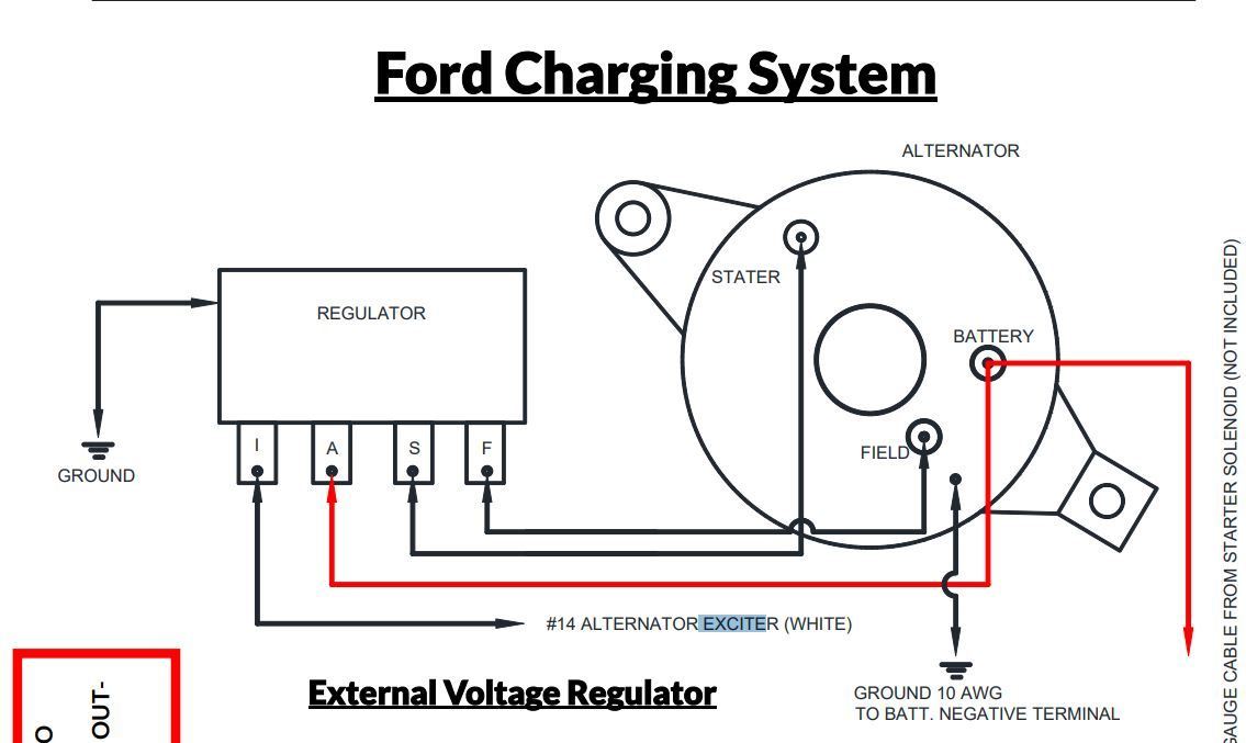
The "3-wire" designation refers to the three essential wires connected to the alternator:
- Battery (BAT) Terminal: A heavy-gauge wire connecting the alternator directly to the positive (+) terminal of the battery. This wire carries the charging current.
- Stator (STA) Terminal: This terminal provides a signal to the voltage regulator about the alternator's output frequency. It is often not used in a 3-wire setup and can be left unconnected but is still a required terminal.
- Ignition (IGN) or Sense (S) Terminal: This terminal provides a voltage reference to the voltage regulator. It senses the voltage at a specific point in the electrical system (ideally close to the battery) and adjusts the alternator's output to maintain the desired voltage at that point.
Symbols and Wiring Diagram Conventions
Understanding the symbols used in the wiring diagram is essential for proper interpretation. Here are some common symbols and conventions:
- Solid Lines: Represent wires. Thicker lines generally indicate heavier-gauge wires carrying higher currents.
- Dotted Lines: Sometimes used to indicate wires that are optional or have a secondary function.
- Color Coding: Wires are often color-coded (e.g., Red for power, Black for ground). While Ford used specific color schemes, always verify with your vehicle's service manual. Do not assume the color of the wire.
- Ground Symbol (┴): Indicates a connection to the vehicle's chassis, which serves as a common ground point.
- Battery Symbol (+/-): Indicates the battery and its polarity.
- Resistors (Ω): Zigzag line representing a resistor, which limits current flow.
- Fuses/Circuit Breakers: Protect the circuit from overcurrent. They are often depicted as a small box with a line through it.
A typical 3-wire Ford alternator wiring diagram will show:
- The BAT terminal connected directly to the battery positive (+) terminal, often through a fusible link.
- The STA terminal is typically unused in a 3-wire setup, and the diagram may show it disconnected or going to a diagnostic port.
- The IGN/S terminal connected to a switched 12V source (meaning it only receives power when the ignition is on). This source is often tapped from the ignition switch or a nearby fuse box.
We have the file for the Ford 3G alternator wiring diagram. You can download it from [Provide Download Link Here] after this article.
How It Works
The 3-wire Ford alternator's operation can be broken down as follows:
- When the engine starts, the alternator begins to spin, driven by a belt connected to the crankshaft pulley.
- The IGN/S terminal receives 12V power from the ignition switch, signaling the voltage regulator to start working.
- The voltage regulator monitors the voltage at the IGN/S terminal. This is the "sense" function – it's sensing the voltage *at the point where the wire is connected*.
- Based on the sensed voltage, the regulator controls the amount of current flowing through the alternator's field windings. This current generates a magnetic field.
- The spinning rotor within the alternator cuts through this magnetic field, inducing a current in the stator windings. This current is rectified (converted from AC to DC) and outputted through the BAT terminal.
- The alternator charges the battery and supplies power to the vehicle's electrical system. The voltage regulator constantly adjusts the field current to maintain a stable output voltage (around 14 volts), compensating for changes in engine speed and electrical load.
The key to the 3-wire design is the remote voltage sensing provided by the IGN/S terminal. By sensing the voltage at a point further away from the alternator (closer to the battery or the vehicle's electrical load center), the regulator can compensate for voltage drops in the wiring and ensure that the battery and electrical components receive the correct voltage.
Real-World Use: Basic Troubleshooting Tips
Here are some common troubleshooting scenarios and how the wiring diagram can help:
- Battery Light Stays On: This usually indicates a problem with the charging system. Check the voltage at the BAT terminal with the engine running. It should be around 13.8-14.5 volts. If it's significantly lower, the alternator may be faulty, the voltage regulator may be bad, or there could be a wiring issue. Use a multimeter to check for voltage drops along the BAT wire and ensure it has a solid connection at both ends. Also, make sure that the IGN wire has the same voltage as the battery when the key is on.
- Overcharging (Battery Boiling): This indicates a faulty voltage regulator. Replace the alternator. Also, check the IGN/S wire for a good connection. A bad connection here can cause the regulator to "think" the voltage is lower than it actually is, leading to overcharging.
- No Charging: Check the IGN/S wire for 12V power with the ignition on. If there's no power, trace the wire back to the ignition switch or fuse box and repair any breaks or loose connections. Also, inspect the fusible link on the BAT wire. A blown fusible link will prevent the alternator from charging.
- Intermittent Charging: This can be caused by loose connections or corroded terminals. Carefully inspect all connections at the alternator, battery, and ignition switch. Clean and tighten any suspect connections.
Safety Precautions
Working with automotive electrical systems can be dangerous. Keep these safety precautions in mind:
- Disconnect the Battery: Always disconnect the negative (-) battery terminal before working on the electrical system. This prevents accidental shorts and potential electrical shocks.
- Work in a Well-Ventilated Area: Batteries can produce explosive gases.
- Use Proper Tools: Use insulated tools to avoid accidental shorts.
- Avoid Touching Exposed Wires: Especially when the engine is running.
- Fusible Links and Fuses: Do not bypass or increase the amperage rating of fuses or fusible links. They are there to protect the system from overcurrent. Bypassing them is a fire hazard.
- Capacitors: The alternator contains capacitors that can store a charge even after the battery is disconnected. Discharge these capacitors by briefly connecting a resistor (e.g., a 12V light bulb) across the alternator's terminals.
- Working on the BAT terminal with the engine running carries a risk of severe electric shock. This terminal carries high amperage current.
By understanding the 3-wire Ford alternator regulator wiring diagram and following these safety precautions, you can confidently diagnose and repair charging system issues, perform custom modifications, and ensure your vehicle's electrical system operates reliably. Remember that we have the complete wiring diagram available for download; you can access it at [Provide Download Link Here]. Good luck with your project!