
3 Wire Ford Alternator Wiring Diagram
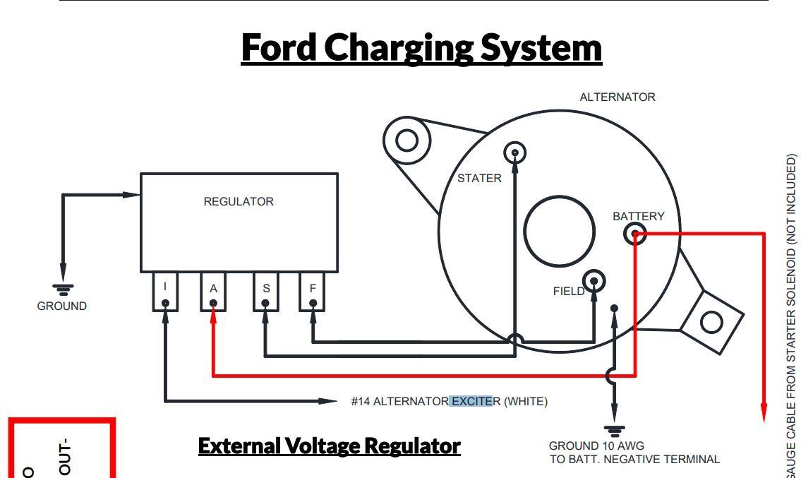
Understanding the 3-wire Ford alternator wiring diagram is crucial for various automotive tasks, from basic repairs and upgrades to more complex modifications and even custom electrical system builds. This guide provides a detailed, yet approachable, explanation of how these systems work, equipping you with the knowledge to confidently diagnose, troubleshoot, and maintain your Ford's charging system. Having a solid grasp of this wiring system allows you to confidently tackle issues such as a dead battery, dimming headlights, or an alternator that simply isn't keeping up with the vehicle's electrical demands. You can download a copy of the diagram at the end of the article.
Why This Diagram Matters
The 3-wire Ford alternator is a popular choice, known for its reliability and relative simplicity. Mastering its wiring diagram unlocks several benefits:
- Diagnosis and Repair: Precisely identify faulty components and wiring issues within the charging system.
- Upgrades: Safely install a higher-output alternator to support aftermarket accessories like powerful audio systems or off-road lighting.
- Customization: Integrate the alternator into custom vehicle builds or engine swaps, ensuring proper charging functionality.
- Performance Improvement: Understand how the charging system impacts overall vehicle performance and optimize it for better efficiency.
- Saving Money: Avoid costly trips to the mechanic by confidently diagnosing and fixing charging system problems yourself.
Key Specs and Main Parts
Before diving into the diagram, let's cover the core components and specifications of a typical 3-wire Ford alternator system:
- Alternator: The heart of the charging system, converting mechanical energy from the engine into electrical energy. Its output voltage is typically around 13.8-14.4 volts.
- Voltage Regulator: Controls the alternator's output voltage, preventing overcharging and damage to the battery and other electrical components. In a 3-wire setup, the voltage regulator can be internal or external.
- Battery: Stores electrical energy and provides power to start the engine and run accessories when the engine is off.
- Wiring Harness: Connects all the components, carrying electrical current between them.
- Fusible Links/Fuses: Protect the circuits from overcurrent and short circuits.
- Ground Connections: Essential for completing the electrical circuits. A poor ground can cause a wide range of electrical problems.
The '3 wires' in a 3-wire alternator system typically refer to the following:
- Battery (B+) Terminal: The main output wire that connects directly to the positive (+) terminal of the battery. This wire carries the charging current to the battery and powers the vehicle's electrical system.
- Stator (S) Wire: This wire senses the voltage at a remote point in the electrical system, usually at the battery or the main power distribution point. This allows the voltage regulator to compensate for voltage drop in the wiring and ensure that the battery receives the correct charging voltage.
- Ignition (I) Wire: Also called the "exciter wire," this wire provides a small amount of current from the ignition switch to initially energize the alternator's field windings when the engine is started. Once the alternator starts producing power, it becomes self-exciting.
Symbols - Deciphering the Diagram
Understanding the symbols used in the wiring diagram is key to interpreting its information accurately:
- Solid Lines: Represent wires. Thicker lines usually indicate wires carrying higher current.
- Dashed Lines: May indicate shielded wires or connections behind the dashboard.
- Color Codes: Different colors represent different wires and their functions. Standard color codes are used in automotive wiring, such as red for power, black for ground, and yellow for ignition. Always refer to the specific wiring diagram for your vehicle to confirm the color codes.
- Circles: Represent connections or terminals.
- Rectangles: Often represent components like fuses, relays, or the voltage regulator.
- Ground Symbol (usually three horizontal lines, decreasing in length): Indicates a connection to the vehicle's chassis or ground. Proper grounding is critical for the entire system to function properly.
- Battery Symbol (+/-): Shows the battery's positive and negative terminals.
How It Works
The 3-wire alternator system works by converting mechanical energy from the engine into electrical energy to charge the battery and power the vehicle's electrical components. Here's a breakdown of the process:
- Engine Start: When the ignition key is turned to the "start" position, the starter motor engages, cranking the engine. The ignition wire (I) provides a small amount of current to the alternator's field windings. This is called excitation.
- Alternator Operation: As the engine spins the alternator's rotor, the rotating magnetic field induces an electrical current in the stator windings. This AC (Alternating Current) current is then rectified (converted to DC – Direct Current) by diodes within the alternator.
- Voltage Regulation: The voltage regulator monitors the system voltage, using the stator (S) wire as a feedback. It adjusts the current flowing through the field windings to control the alternator's output voltage. If the voltage is too low, the regulator increases the field current, increasing the output. If the voltage is too high, the regulator decreases the field current, decreasing the output.
- Charging the Battery: The regulated DC voltage from the alternator is then sent to the battery via the battery (B+) terminal wire. This current replenishes the battery's charge, keeping it fully charged while the engine is running.
- Powering the Vehicle: The alternator also provides power to the vehicle's electrical system, including the headlights, radio, and other accessories.
Real-World Use - Basic Troubleshooting
Here are some basic troubleshooting tips based on the 3-wire alternator wiring diagram:
- No Charge: If the battery isn't charging, check the following:
- B+ Wire: Ensure the connection is clean and tight at both the alternator and battery terminals. Use a multimeter to check for voltage between the alternator B+ terminal and ground while the engine is running (should be around 13.8-14.4V).
- S Wire: Verify that the S wire is properly connected to a voltage source (e.g., the battery positive terminal or a distribution block) and that it is receiving voltage when the engine is running.
- I Wire: Confirm that the I wire is receiving voltage from the ignition switch when the key is in the "run" position.
- Ground Connections: Check and clean all ground connections, including the alternator's ground and the battery's ground. A poor ground is a common cause of charging problems.
- Fuses/Fusible Links: Inspect all fuses and fusible links in the charging circuit for damage. Replace any blown fuses.
- Overcharging: If the battery is overcharging (voltage above 14.5V), the voltage regulator is likely faulty and needs to be replaced. Also, double-check the S-wire connection. A bad S-wire connection can cause the regulator to think the voltage is lower than it actually is, causing it to overcharge.
- Dimming Headlights: Dimming headlights can indicate a low charging voltage or a faulty alternator. Check the B+ wire, S wire, and ground connections.
Safety
Working with electrical systems can be dangerous. Always follow these safety precautions:
- Disconnect the Battery: Always disconnect the negative (-) battery terminal before working on the electrical system.
- Use Insulated Tools: Use insulated tools to prevent accidental shorts and electric shocks.
- Wear Safety Glasses: Wear safety glasses to protect your eyes from sparks and debris.
- Be Careful Around the Alternator: The alternator's output voltage can be high enough to cause a shock. Avoid touching the B+ terminal while the engine is running.
- Proper Grounding: Ensure all ground connections are clean and secure.
Working on the electrical system of a vehicle carries inherent risks. If you are not comfortable working with electrical systems, it is best to consult a qualified mechanic.
We have a detailed wiring diagram file available for download. Understanding and using it, you will be equipped with the knowledge to confidently diagnose, troubleshoot, and maintain your Ford's charging system.