3 Wire Fuel Gauge Wiring Diagram
So, you're looking to get your hands dirty with a 3-wire fuel gauge? Smart move! Understanding how these systems work isn't just about fixing problems; it's about truly understanding your car and being able to customize or even build your own gauges if you’re inclined. This article will walk you through the ins and outs of a typical 3-wire fuel gauge wiring diagram, giving you the knowledge you need to diagnose issues, make repairs, or even upgrade your existing system.
Purpose of Understanding the 3-Wire Fuel Gauge Diagram
Why bother learning all this? Well, several reasons. First, if your fuel gauge is acting up (showing empty when you know it's full, or wildly fluctuating), understanding the wiring is crucial for pinpointing the problem. Is it the sending unit in the tank? A broken wire? A faulty gauge? The diagram is your roadmap. Second, if you’re modifying your car – say, swapping in a different fuel tank or installing aftermarket gauges – knowing how the wiring works prevents costly mistakes and ensures proper function. And finally, even if everything’s working fine, understanding the system's fundamentals can give you a greater appreciation for automotive technology.
Key Specs and Main Parts
Before diving into the diagram itself, let's review the core components:
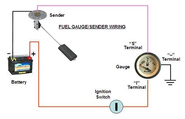
- Fuel Gauge: The instrument on your dashboard that displays the fuel level. It’s essentially a voltmeter, measuring the voltage drop across a resistor network.
- Fuel Sending Unit (Float): Located inside the fuel tank, this unit uses a float arm attached to a variable resistor (a resistor whose resistance can be changed). As the fuel level changes, the float arm moves, changing the resistance value.
- Wiring: This is what connects the gauge, sending unit, and power source. In a 3-wire system, you typically have:
- Power (12V): Supplies the necessary voltage for the gauge to operate.
- Ground: Provides a return path for the electrical current.
- Signal Wire: Carries the varying resistance signal from the sending unit to the gauge. This wire is the key to the entire system.
Symbols and Conventions in the Wiring Diagram
A wiring diagram is like a technical language. Understanding the symbols is critical. Here's a breakdown of what you might typically see:
- Solid Lines: Represent wires. Thicker lines might indicate higher current capacity.
- Dashed Lines: Sometimes used to represent shielded wires or wires that are part of a harness.
- Colors: Wires are often color-coded (e.g., Red for power, Black for ground, Yellow or Green for signal). Refer to your vehicle's specific wiring diagram for the exact color codes.
- Ground Symbol: Usually three horizontal lines, decreasing in length, connected vertically (similar to an inverted pyramid) indicates where components connect to the vehicle's chassis for grounding.
- Battery Symbol: Shows the battery, indicating the source of DC power (typically 12V).
- Fuse Symbol: A small box or zigzag line, representing a fuse for circuit protection.
- Resistor Symbol: A zigzag line, representing a component that resists the flow of current. In the sending unit, the variable resistor will often have an arrow through it.
- Gauge Symbol: Often represented as a circle with "E" and "F" markings inside, or a stylized gauge needle.
Important Note: Always refer to the specific wiring diagram for your vehicle's make, model, and year. General diagrams can be helpful, but the exact wire colors and component locations can vary considerably.
How the 3-Wire Fuel Gauge Works
Here’s the magic behind the 3-wire system:
- The Sending Unit Changes Resistance: As the fuel level rises, the float moves upwards, causing the variable resistor in the sending unit to decrease its resistance. Conversely, as the fuel level drops, the float moves downwards, increasing the resistance.
- Voltage Division: The fuel gauge and the sending unit form a series circuit. The sending unit's variable resistance, combined with the gauge's internal resistance, creates a voltage divider. This means the voltage at the signal wire changes depending on the sending unit's resistance.
- The Gauge Interprets the Voltage: The fuel gauge is essentially a voltmeter calibrated to display fuel level. It measures the voltage drop across its internal resistance. A higher voltage (lower resistance at the sending unit – full tank) results in the gauge indicating "Full," while a lower voltage (higher resistance at the sending unit – empty tank) results in the gauge indicating "Empty."
Think of it like this: The sending unit acts like a volume knob controlling the amount of electricity flowing to the gauge. The gauge then translates that flow into a reading on your dashboard.
Real-World Use and Basic Troubleshooting
Okay, let's get practical. Here are a few common issues and how the wiring diagram can help:
- Gauge Always Reads Empty:
- Possible Cause: Open circuit (broken wire) in the signal wire, faulty sending unit, or faulty gauge.
- Troubleshooting: Use a multimeter to check for voltage at the gauge's signal wire with the ignition on. If there’s no voltage, trace the signal wire back to the sending unit, checking for breaks or loose connections. Test the sending unit’s resistance directly – it should change as you manually move the float arm.
- Gauge Always Reads Full:
- Possible Cause: Short circuit (wire touching ground) in the signal wire, faulty sending unit (shorted to ground), or faulty gauge.
- Troubleshooting: Check for continuity between the signal wire and ground. If there is continuity, there's a short. Disconnect the sending unit – if the gauge now reads correctly, the sending unit is the problem.
- Gauge Fluctuates Wildly:
- Possible Cause: Loose connection in the signal wire, corroded terminals, or a failing sending unit with erratic resistance.
- Troubleshooting: Inspect all connections in the fuel gauge circuit, especially at the sending unit and gauge. Clean any corroded terminals. If the connections are good, the sending unit may be failing and need replacement.
Using a Multimeter: A multimeter is your best friend here. Learn how to use it to check for voltage, continuity (checking for breaks in a circuit), and resistance. There are tons of great online resources on how to use a multimeter for automotive electrical testing.
Safety Considerations
Fuel systems are inherently dangerous. Exercise extreme caution when working around fuel tanks and fuel lines. Here's a quick rundown:
- Disconnect the Battery: Always disconnect the negative battery terminal before working on any electrical system.
- Ventilation: Work in a well-ventilated area to avoid inhaling fuel vapors.
- No Smoking/Open Flames: Absolutely no smoking or open flames near the fuel tank.
- Fuel Spillage: Have absorbent materials (like rags or kitty litter) readily available to clean up any fuel spills immediately.
- Fuel Tank Access: Always follow the manufacturer's instructions for accessing the fuel tank. Some tanks are accessible from inside the vehicle, while others require lowering the tank.
- Static Electricity: Be aware of static electricity buildup. Ground yourself frequently by touching a bare metal part of the vehicle before handling fuel lines or electrical components. Static discharge can ignite fuel vapors.
Diagram Download
We have a basic 3-wire fuel gauge wiring diagram available for download. Please remember that it's a general representation, and you should always consult the specific wiring diagram for your vehicle. You can find the link below. Use it responsibly and safely!
[Insert Link to Diagram Here - e.g., "Click here to download the 3-Wire Fuel Gauge Wiring Diagram"]
With a little knowledge and the right tools, you can confidently tackle fuel gauge issues and gain a deeper understanding of your vehicle’s electrical system. Good luck, and stay safe!