3 Wire Fuel Sending Unit Wiring Diagram
For the seasoned DIY mechanic, understanding the intricacies of your vehicle's electrical systems is paramount. One crucial system often overlooked but vital for accurate fuel level indication is the 3-wire fuel sending unit. Whether you're tackling a gauge malfunction, planning a fuel cell swap, or simply seeking a deeper understanding of your car's inner workings, grasping the 3-wire fuel sending unit wiring diagram is an invaluable skill. This article will provide a detailed explanation, covering everything from its purpose to practical troubleshooting, ensuring you're well-equipped to tackle any related issues.
Purpose and Importance
Why bother with the fuel sending unit wiring diagram? There are several compelling reasons:
- Accurate Fuel Level Readings: The primary function is to transmit accurate fuel level data to your fuel gauge. Faulty wiring can lead to erratic or inaccurate readings, leaving you stranded or misinformed.
- Troubleshooting Fuel Gauge Problems: When your fuel gauge malfunctions, the wiring diagram becomes your roadmap to diagnose the issue. You can systematically test each wire and connection to pinpoint the source of the problem.
- Aftermarket Fuel Cell Installation: Swapping your stock fuel tank for an aftermarket fuel cell often requires adapting the existing wiring to the new sending unit. A clear understanding of the diagram is essential for a successful and safe installation.
- Custom Gauge Integrations: Integrating aftermarket gauges often means interfacing with the existing fuel sending unit wiring. The diagram helps you identify the correct wires for splicing and connecting.
- Preventing Electrical Fires: Incorrect wiring can lead to short circuits and potentially dangerous electrical fires, especially in a fuel-rich environment. A thorough understanding of the diagram ensures proper connections and reduces the risk of fire.
Key Specs and Main Parts
Before diving into the diagram itself, let's define the key components and specifications involved:
- Fuel Sending Unit: Located inside the fuel tank, this unit consists of a float, a variable resistor (also called a potentiometer), and electrical terminals. The float rises and falls with the fuel level, changing the resistance value.
- Float: A buoyant component, typically made of plastic or foam, that rests on the fuel surface. Its movement dictates the position of the potentiometer.
- Potentiometer (Variable Resistor): A three-terminal resistor with a sliding or rotating contact that forms an adjustable voltage divider. As the float moves, it changes the potentiometer's resistance, affecting the voltage signal sent to the fuel gauge. The resistance of a potentiometer is measured in ohms.
- Fuel Gauge: Located on the instrument cluster, the fuel gauge receives the voltage signal from the sending unit and displays the fuel level.
- Wiring Harness: The collection of wires that connect the fuel sending unit to the fuel gauge and the vehicle's electrical system.
- Ground Wire: Provides a return path for the electrical current, ensuring a stable and accurate signal.
- Power Wire (Voltage Supply): Provides power to the sending unit and gauge, usually 12V DC.
- Signal Wire: The wire that carries the variable voltage signal from the sending unit to the fuel gauge. This voltage changes depending on the fuel level.
Symbols and Wiring Diagram Explanation
A 3-wire fuel sending unit wiring diagram uses standard electrical symbols and color codes. Understanding these symbols is crucial for interpreting the diagram accurately.
- Solid Lines: Represent wires. The thickness of the line does not typically indicate wire gauge (thickness).
- Dashed Lines: Can represent shielded wiring, ground connections, or alternative circuit paths.
- Color Codes: Wires are often color-coded for easy identification. Common colors include:
- Black (BLK): Ground.
- Red (RED): Power (typically +12V).
- Yellow (YEL), Green (GRN), Blue (BLU): Signal wires (specific color varies depending on the vehicle manufacturer).
- Ground Symbol ( ┴ ): Indicates a connection to the vehicle's chassis ground.
- Resistor Symbol ( ▭ ): Represents the variable resistor (potentiometer) within the sending unit.
- Voltage Source (+V): Indicates a connection to the vehicle's electrical system, providing a specific voltage (usually 12V).
- Fuel Gauge Symbol: A stylized representation of the fuel gauge itself, often including a needle and fuel level markings.
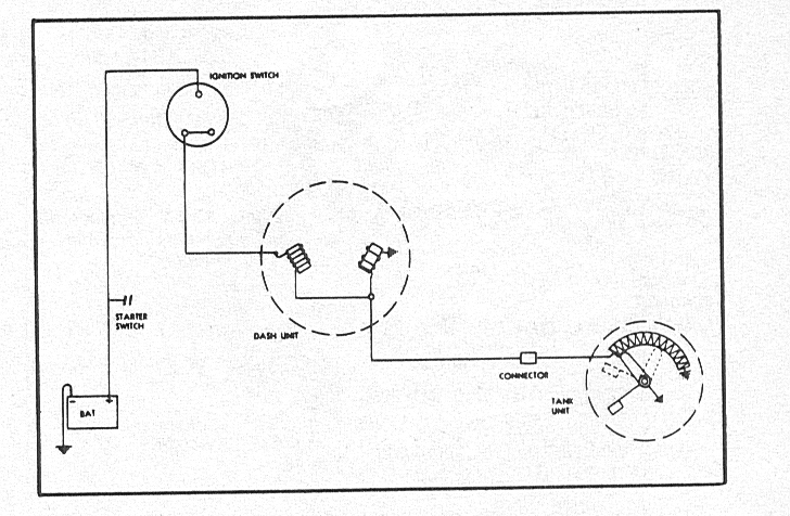
A typical 3-wire fuel sending unit diagram will show three wires connected to the sending unit:
- Ground Wire: Connects the sending unit to the vehicle's chassis ground. This provides a stable reference point for the electrical circuit.
- Power Wire: Supplies power (typically 12V) to the sending unit. This voltage is used to create the variable signal sent to the gauge.
- Signal Wire: Transmits the variable voltage signal from the sending unit to the fuel gauge. The voltage level on this wire changes proportionally to the fuel level.
How It Works
The 3-wire fuel sending unit operates based on a simple principle: Ohm's Law. The potentiometer within the sending unit acts as a voltage divider. The power wire provides a constant voltage (e.g., 12V), and the potentiometer divides this voltage based on its resistance. The resistance, in turn, is determined by the position of the float.
- Fuel Level Changes: As the fuel level rises or falls, the float moves accordingly.
- Potentiometer Adjustment: The float's movement adjusts the position of the potentiometer's wiper arm, changing its resistance.
- Voltage Division: The potentiometer divides the input voltage (from the power wire) based on its resistance. A lower resistance results in a lower voltage output on the signal wire, and vice versa.
- Signal Transmission: The signal wire carries this variable voltage to the fuel gauge.
- Gauge Indication: The fuel gauge interprets the voltage signal and displays the corresponding fuel level on the instrument cluster. A higher voltage usually indicates a higher fuel level, while a lower voltage indicates a lower fuel level.
Think of it like a dimmer switch for voltage. The fuel float moves the dimmer (potentiometer), changing the brightness (voltage) sent to the lightbulb (fuel gauge).
Real-World Use: Basic Troubleshooting Tips
Here are some practical troubleshooting tips when dealing with a 3-wire fuel sending unit:
- Gauge Reads Empty All the Time:
- Check the ground wire: A faulty ground connection is a common culprit. Ensure the ground wire is securely connected to the chassis and free from corrosion.
- Check the power wire: Verify that the power wire is receiving the correct voltage (typically 12V). Use a multimeter to test the voltage at the sending unit connector.
- Test the sending unit resistance: Disconnect the sending unit and use a multimeter to measure the resistance across the terminals. Compare the readings to the expected resistance range (refer to your vehicle's service manual). The resistance should change smoothly as you manually move the float arm. An open circuit (infinite resistance) or a short circuit (zero resistance) indicates a faulty sending unit.
- Gauge Reads Full All the Time:
- Check for a short circuit: A short circuit in the signal wire can cause the gauge to read full. Inspect the wiring harness for any signs of damage or frayed wires.
- Test the sending unit resistance: Similar to the previous scenario, test the resistance to rule out a faulty sending unit.
- Erratic or Inaccurate Readings:
- Check the wiring connections: Loose or corroded connections can cause intermittent signal disruptions. Clean and tighten all connections.
- Inspect the sending unit float: Ensure the float is not damaged or obstructed. A damaged float can sink or become stuck, leading to inaccurate readings.
- Check fuel gauge is working properly Disconnect the sending unit and manually input a known voltage level using a potentiometer inline. This will determine if the fault is in the sending unit or the gauge itself.
Safety Precautions
Working with fuel systems involves inherent risks. Always take the following safety precautions:
- Disconnect the Battery: Before working on any electrical components, disconnect the negative terminal of the battery to prevent accidental short circuits.
- Work in a Well-Ventilated Area: Fuel vapors are flammable and can be harmful if inhaled. Ensure adequate ventilation to prevent the buildup of vapors.
- Use Proper Tools: Use insulated tools to avoid electrical shocks.
- Avoid Sparks and Open Flames: Never smoke or use open flames near the fuel tank or fuel lines.
- Fuel is Toxic Avoid direct contact with fuel. Wear gloves and eye protection. Clean up any spills immediately.
- Know your Flammability Basics Familiarize yourself with the components that are potentially risky.
Fuel vapors are highly flammable. Exercise extreme caution when working near the fuel tank or fuel lines.
With this detailed explanation and the provided wiring diagram, you should be well-equipped to understand, troubleshoot, and repair 3-wire fuel sending unit systems. Remember to always prioritize safety and consult your vehicle's service manual for specific wiring configurations and resistance values.
We have a downloadable PDF version of a generic 3-wire fuel sending unit diagram. It will allow you to have a clear visual aid while working on your project. Please let us know if you require it, and we can provide it to you.