
3 Wire Nissan Alternator Wiring Diagram
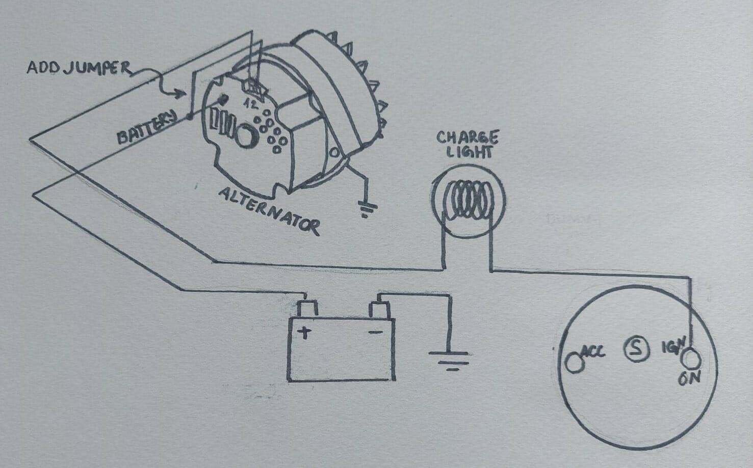
Understanding the 3-wire Nissan alternator wiring diagram is crucial for anyone tackling electrical repairs, performance modifications, or even just trying to better comprehend how their vehicle's charging system functions. This guide breaks down the diagram, explains its components, and equips you with the knowledge to diagnose and troubleshoot common issues. We'll assume you're familiar with basic automotive electrical concepts and safety practices.
Purpose and Importance
Why bother with a wiring diagram? Several compelling reasons exist:
- Troubleshooting: When your battery isn't charging, or you suspect an alternator issue, the diagram is your roadmap to pinpointing the fault.
- Upgrades and Swaps: If you're upgrading your alternator to a higher-output model, or swapping in a different engine, the diagram ensures proper wiring and compatibility.
- Learning: Deepening your understanding of your vehicle's electrical system empowers you to perform more complex repairs and modifications.
- Restoration Projects: During a complete vehicle restoration, having the correct wiring diagram is invaluable for correctly connecting the charging system.
Key Specs and Main Parts
Before diving into the diagram, let's identify the key components involved in a typical 3-wire Nissan alternator system:
- Alternator: The heart of the system, converting mechanical energy from the engine into electrical energy to charge the battery and power electrical loads.
- Battery: The energy storage device that powers the vehicle's electrical system when the engine isn't running or when the alternator's output is insufficient.
- Voltage Regulator: This controls the alternator's output voltage to prevent overcharging and damage to the battery and other electrical components. Most modern alternators, especially in 3-wire configurations, have an internal voltage regulator.
- Ignition Switch: Supplies power to the alternator's regulator circuit when the key is in the "on" or "run" position.
- Wiring Harness: The bundle of wires that connects all the components.
- Fuses/Fusible Links: Protection devices that prevent damage from overcurrent or short circuits. Crucially important for safety.
The "3 wires" themselves typically represent:
- Battery (B+): A heavy-gauge wire that carries the alternator's output to the battery positive terminal, and typically to the main power distribution system.
- Ignition (IG or Sense): A smaller-gauge wire that connects to the ignition switch, providing power to the voltage regulator when the key is on. This wire often also acts as a 'sense' wire to allow the alternator to compensate for voltage drop in the system.
- Ground: A wire connecting the alternator case to the vehicle's chassis ground, ensuring a good electrical return path. A proper ground connection is critical for proper alternator operation.
Understanding the Wiring Diagram: Symbols and Colors
Wiring diagrams use standardized symbols and color codes to represent components and wiring. Here's a breakdown of common elements:
- Lines: Solid lines represent wires. Dashed lines may indicate shielded cables or internal connections within a component.
- Color Codes: Each wire is typically identified by a color code (e.g., Red, Blue, Black). These codes are often abbreviated (e.g., R, BL, BK). Refer to the diagram's legend to decode the abbreviations. Knowing these color codes is invaluable for tracing wires through the harness.
- Component Symbols: Each component (alternator, battery, switch, etc.) has a specific symbol. These symbols are usually labeled.
- Ground Symbol: Typically a series of downward-pointing lines, indicating a connection to the vehicle's chassis ground.
- Fuse Symbol: A wavy line within a rectangle or circle.
- Voltage Regulator (Internal): Often shown as a box integrated within the alternator symbol.
Example:
A solid red line labeled "B+" connected to a symbol resembling a battery indicates the main charging wire running from the alternator to the battery positive terminal.
How It Works: A Simplified Explanation
The 3-wire alternator system operates as follows:
- When the engine starts and the ignition switch is turned to the "on" position, power is supplied to the alternator's voltage regulator via the "IG" (Ignition) wire.
- The voltage regulator monitors the battery voltage and controls the amount of current supplied to the alternator's field windings (rotor).
- As the alternator rotor spins, it generates an alternating current (AC) in the stator windings.
- The AC current is then rectified (converted to direct current or DC) by diodes within the alternator.
- The resulting DC current is then outputted via the "B+" wire to charge the battery and power the vehicle's electrical loads.
- The "Sense" wire, if present (often combined with the IG wire), allows the voltage regulator to compensate for voltage drops in the wiring between the alternator and the battery. This ensures the battery receives the correct charging voltage, even under heavy load. If voltage drop is substantial, the voltage at the battery will be less than the voltage at the alternator.
- The ground wire provides the necessary return path for the electrical current.
Real-World Use: Basic Troubleshooting Tips
Here are some common issues and troubleshooting tips:
- Battery Not Charging:
- Check the B+ wire for continuity and proper connection to the battery.
- Verify that the IG wire is receiving power when the ignition is on.
- Inspect the alternator ground connection for corrosion or looseness.
- Test the alternator's output voltage with a multimeter. A healthy alternator should output around 13.5-14.5 volts when the engine is running.
- If the alternator tests good but the battery still isn't charging, investigate the battery itself.
- Overcharging:
- Suspect a faulty voltage regulator. Replacing the alternator (which includes the regulator in most cases) is often the easiest solution.
- Check for a short circuit in the wiring harness that could be bypassing the regulator.
- Warning Light On:
- Most vehicles have a warning light on the dashboard that illuminates when the charging system is not functioning correctly. This could indicate a problem with the alternator, voltage regulator, or wiring.
- Use a scan tool to check for diagnostic trouble codes (DTCs) related to the charging system.
Safety Considerations
Working with automotive electrical systems can be hazardous. Always observe these safety precautions:
- Disconnect the Battery: Before working on any electrical component, disconnect the negative (-) battery cable to prevent short circuits and electric shock.
- Use Proper Tools: Use insulated tools to avoid accidental shorts.
- Wear Safety Glasses: Protect your eyes from sparks or debris.
- Be Careful with High-Current Circuits: The B+ wire carries a significant amount of current. Avoid touching it while the engine is running.
- Fuses are Your Friends: Never bypass a fuse or fusible link. These devices are designed to protect the electrical system from damage. Replacing a blown fuse with one of a higher amperage is extremely dangerous!
Important The B+ terminal on the alternator is *always* hot. Even with the key off, it's directly connected to the battery. Be extremely careful around this terminal!
Disclaimer: Electrical work should be performed by qualified technicians. The information provided here is for informational purposes only and should not be considered a substitute for professional advice.
To aid your understanding, we have a detailed 3-wire Nissan alternator wiring diagram file available for download. Contact us, and we will provide it to you. Remember to always consult your vehicle's specific repair manual for the most accurate information.