
3 Wire Pressure Sensor Wiring Diagram
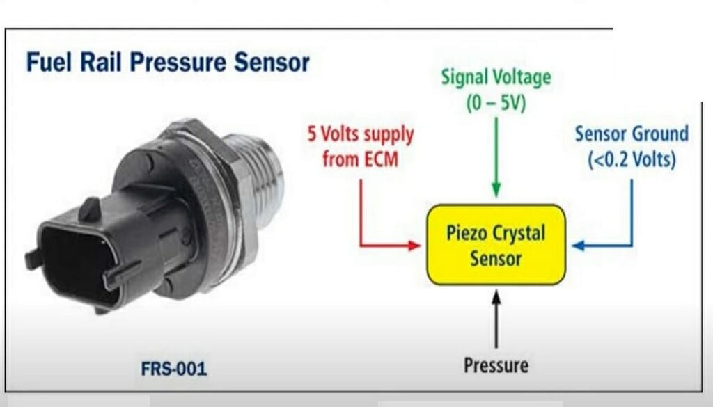
Let's talk about 3-wire pressure sensors. You've probably encountered them if you've been tinkering with your car, especially if you're dealing with engine management systems, fuel injection, or even things like air suspension. Understanding how these sensors are wired, and more importantly, what the wiring diagram tells you, is crucial for accurate diagnostics, reliable repairs, and successful modifications. This article will break down the 3-wire pressure sensor wiring diagram, giving you the knowledge you need to confidently troubleshoot and work with these components.
Why Bother Understanding the Wiring Diagram?
Why should you care about this? Well, a 3-wire pressure sensor wiring diagram is your roadmap. It allows you to:
- Diagnose Problems: If your engine is running rough, or your fuel economy has tanked, a faulty pressure sensor could be the culprit. The wiring diagram helps you pinpoint the issue quickly.
- Perform Repairs: Know what wires to check with a multimeter. No more guessing.
- Make Modifications: Swapping in a new sensor? Upgrading your fuel system? The diagram ensures you connect everything correctly, preventing damage and ensuring optimal performance.
- Learn the Fundamentals: Grasping the wiring helps you understand how the entire system operates.
Basically, understanding this diagram is essential for anyone who wants to move beyond simply replacing parts and actually understand what's going on under the hood.
Key Specs and Main Parts of a 3-Wire Pressure Sensor
Before we dive into the diagram, let's quickly cover the basics of the sensor itself.
A 3-wire pressure sensor is a transducer – meaning it converts pressure into an electrical signal. This signal is then sent to the Engine Control Unit (ECU) or another control module, which uses the information to adjust various engine parameters (like fuel injection timing and air-fuel ratio).
Here are the three wires you'll always find:
- Power (Vcc or +V): This wire provides the sensor with the necessary voltage to operate. Typically, this is a 5V signal, but you should always confirm the specific voltage requirement for your sensor using the manufacturer's datasheet.
- Ground (GND): This provides the return path for the electrical current. It's crucial for a stable and accurate reading.
- Signal (Vout): This wire carries the output voltage signal from the sensor, which varies proportionally with the measured pressure. This is the wire the ECU monitors.
The sensor itself contains a pressure-sensitive element (often a diaphragm or strain gauge) that changes its electrical resistance in response to pressure. This change in resistance is then converted into a voltage signal.
Decoding the Wiring Diagram: Symbols and Colors
Now, let's decipher the wiring diagram. This is where things get visual. Wiring diagrams use standardized symbols and color codes to represent different components and connections.
Lines:
- Solid Lines: Represent wires connecting different components.
- Dashed Lines: Might indicate shielding around a wire to prevent electrical interference.
- Lines Crossing: Usually indicate wires that pass over each other without making a connection. If a connection exists, a dot is typically shown at the intersection.
Colors:
Wire colors are usually abbreviated in wiring diagrams. Here are some common ones:
- Red (R): Typically used for power.
- Black (BK): Typically used for ground.
- White (W): Often used for signal or ground.
- Green (G): Often used for signal or ground.
- Blue (BL): Often used for signal.
- Yellow (Y): Often used for signal.
Important: Wire colors can vary by manufacturer and even by model year. Always consult the specific wiring diagram for *your* vehicle.
Icons:
You'll also see icons representing the sensor itself, the ECU, connectors, and other related components. The sensor icon is typically a square or rectangle with the three terminals (Vcc, GND, Vout) labeled.
A connector is often depicted as a series of interlocking shapes, indicating a physical connection point in the wiring harness.
The ECU, sometimes labeled PCM (Powertrain Control Module), will be depicted as a box. The diagram will show which pin numbers on the ECU connector the sensor wires connect to.
How It Works: From Pressure to Signal
Let's trace the signal flow:
- Power Supply: The ECU provides a stable voltage (typically 5V) to the sensor's Vcc (power) wire.
- Pressure Sensing: The sensor's internal pressure-sensitive element reacts to the pressure being measured.
- Resistance Change: This pressure causes a change in the resistance of the sensor element.
- Voltage Output: The change in resistance alters the voltage at the signal (Vout) wire. This voltage is proportional to the pressure. For example, a higher pressure might result in a higher voltage.
- Signal to ECU: The ECU reads the voltage on the Vout wire.
- Data Interpretation: The ECU uses a predefined calibration curve (a table or formula) to convert the voltage signal into a pressure reading.
- Action Taken: Based on the pressure reading, the ECU adjusts engine parameters like fuel injection, ignition timing, and boost pressure (if applicable).
Think of it like a dimmer switch on a light. The pressure acts like you turning the knob. The higher the pressure, the more the "knob" is turned, and the higher the voltage output.
Real-World Use: Basic Troubleshooting Tips
Okay, now for some practical application. If you suspect a problem with a 3-wire pressure sensor, here's a basic troubleshooting approach using the wiring diagram:
- Visual Inspection: Start by checking the wiring harness for any obvious damage, like frayed wires, corroded connectors, or loose connections. Pay close attention to the connector at the sensor itself.
- Voltage Check (Power Wire): Use a multimeter to check for the correct voltage on the power (Vcc) wire. With the ignition on, you should see approximately 5V (or the specified voltage for your sensor). If you don't, there's likely a problem with the power supply or the wiring leading to the sensor.
- Continuity Check (Ground Wire): Use a multimeter to check for continuity between the ground (GND) wire and a known good ground point on the vehicle's chassis. You should see close to zero resistance. If not, there's a grounding issue.
- Signal Wire Measurement: With the sensor connected and the engine running (or the system under pressure), use a multimeter to measure the voltage on the signal (Vout) wire. The voltage should vary as the pressure changes. Compare this voltage to the expected range specified in the vehicle's service manual or the sensor's datasheet.
- Scan Tool Data: If you have a scan tool (OBDII scanner), check the pressure reading reported by the ECU. Compare this reading to a known good value. If the scan tool shows an implausible reading, and you've verified the wiring and power supply, the sensor itself is likely faulty.
Example: Let's say you're troubleshooting a manifold absolute pressure (MAP) sensor. You check the Vcc wire and find only 2V instead of 5V. This indicates a voltage drop, possibly due to a corroded connector or a damaged wire somewhere in the power supply circuit. The wiring diagram will show you the path of the power wire, allowing you to trace the circuit and find the source of the voltage drop.
Safety First!
Working with electrical systems in a vehicle can be dangerous. Always disconnect the battery before working on any wiring. Be especially careful when working with sensors connected to high-pressure systems (like fuel pressure sensors). Depressurize the system before disconnecting the sensor. Fuel spraying everywhere is a bad day for everyone!
Also, be aware that some components, like the ECU, are sensitive to static electricity. Use proper grounding techniques when handling these components to prevent damage.
Before doing anything, consult your vehicle's service manual or a qualified mechanic if you're unsure about any aspect of the repair.
Now that you understand how to read a 3-wire pressure sensor wiring diagram, you are better prepared to diagnose and repair issues with your car. Understanding these diagrams provides a solid foundation for tackling other automotive electrical challenges. We have a sample file, a typical 3-Wire Pressure Sensor Wiring Diagram, which you can download and use as a reference.